
Humidity measurement device and method

a humidity measurement and humidity technology, applied in the field of measuring instruments, can solve the problems of limited measurement range, high temperature drift, inconvenient measurement and conversion, etc., and achieve the effect of reducing the impact of external factors, improving measurement accuracy, and cancelling system errors

Active Publication Date: 2012-10-11
BEIJING POLYMER SENSING TECH CO LTD
View PDF14 Cites 19 Cited by
  • Summary
  • Abstract
  • Description
  • Claims
  • Application Information

AI Technical Summary

Benefits of technology

[0006]In view of this, according to an embodiment of the present invention, a device for humidity measurement and a method thereof are provided, which can improve the accuracy and stability in humidity measurement.
[0037]In comparison with the prior art, the technical solutions according to the present invention can realize humidity measurement with a single-chip architecture, that is, achieve the activation and measurement of the humidity-sensitive capacitor by a microcontroller with the help of a small number of resistors and capacitors. The simple architecture lowers the impact of external factors on humidity measurement to the minimum level; and the microcontroller carries out both temperature compensation and non-linear compensation of the measured value, which can improve the measurement accuracy to the greatest extent possible. Moreover, an additional follower capacitor is provided in the capacitance measuring circuit, and in calculation the difference between the capacitances of the two branches is used as a variable of the humidity function, thereby cancelling out system errors and improving the measurement accuracy.
[0038]The present invention provides a condensation prevention design by adding a constant-current-driven heating resistor underneath the electrodes of the humidity-sensitive capacitor, to cause temperature difference between the humidity-sensitive capacitor and the ambient environment and prevent condensation, so that continuous humidity measurement can be achieved during the heating process without compromising the function of the product. Meanwhile, capacitance drift of the humidity-sensitive capacitor is reduced, and the humidity-sensitive capacitor's lifetime is increased.
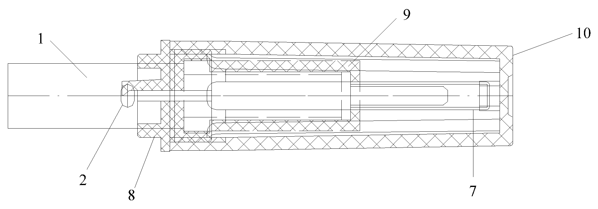
[0039]Furthermore, the exterior structure of the device for humidity measurement according to the present invention adopts a two-layered design including a waterproofing and ventilating housing and a plastic protective housing, which can block off dust and splash without affecting humidity measurement and increase the humidity-sensitive element's lifetime to the greatest extent possible.

Problems solved by technology

The electrical resistance can vary dramatically, and is in a logarithmic relationship with the humidity to be measured, causing inconvenience in measurement and conversion, and limited range of measurement.
However, both types of humidity-sensitive elements have the problem of high-temperature drift, and may have reduced accuracy due to condensation or dust, or even break down or be damaged in severe conditions.

Method used


Image

  • Humidity measurement device and method
  • Humidity measurement device and method
  • Humidity measurement device and method

Examples


first embodiment

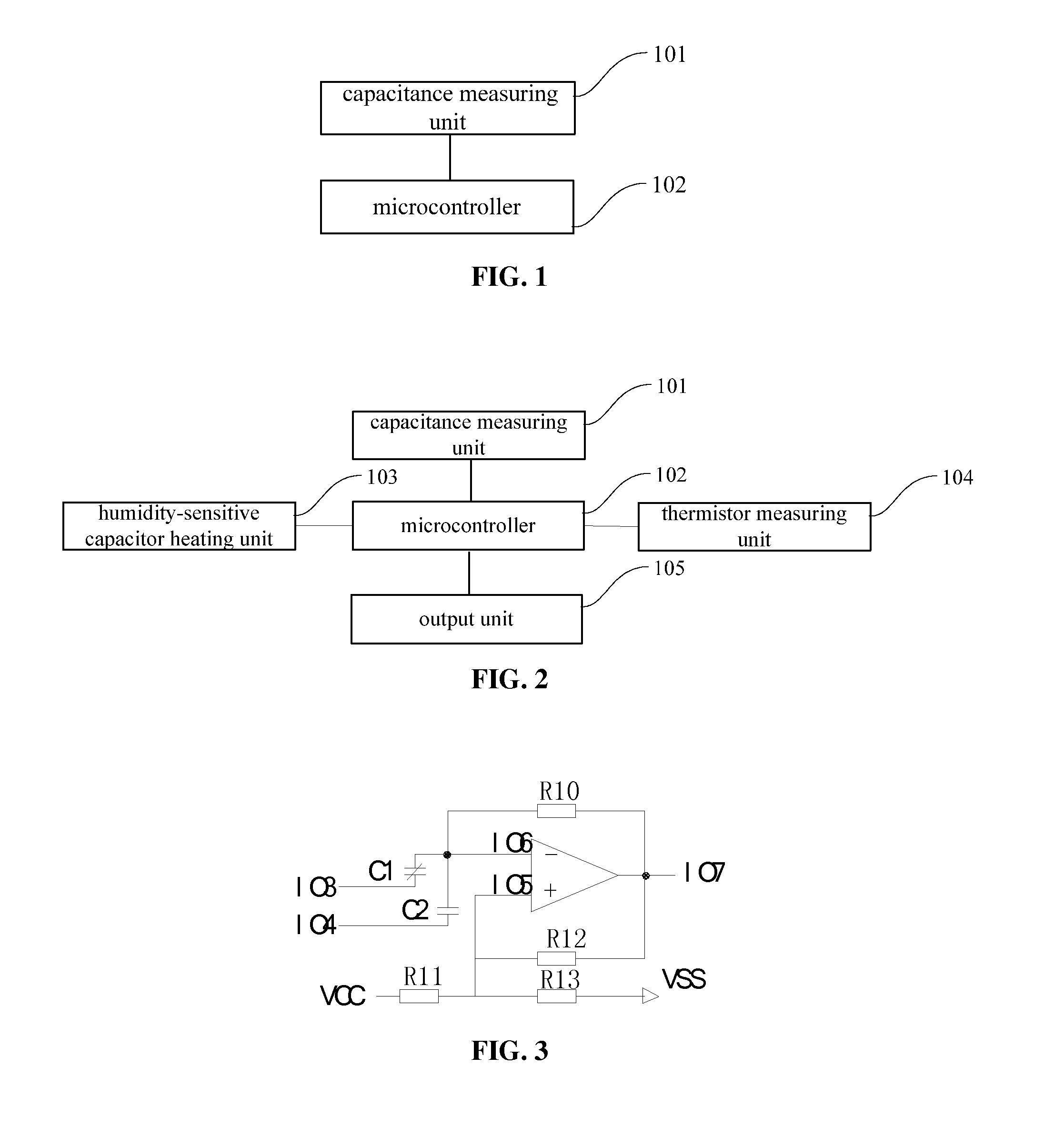
[0071]According to the embodiment of the present invention, an implementation of the capacitance measuring unit is provided. As shown in FIG. 3, the implementation mainly includes the following.

[0072]A capacitor and external resistors and capacitors form a Schmitt trigger, where the capacitors C1 and C2 are charged / discharged through R10. Specifically, C1 is the humidity-sensitive capacitor for measuring ambient temperature; C2 is the reference capacitor for compensating the humidity value measured by C1; and R11, R12 and R13 determine a high threshold V1 and a low threshold V2 at different times. When R12 and R13 are connected in parallel with each other, then both in series to R11, the low threshold V2 is determined. The operating principle of this circuit is described below.

[0073]To measure the humidity-sensitive capacitor C1, a pin IO4 of the microcontroller that is connected to C2 is set at high-impedance, a pin IO3 that is connected to C1 is grounded, and another pin is connec...

second embodiment

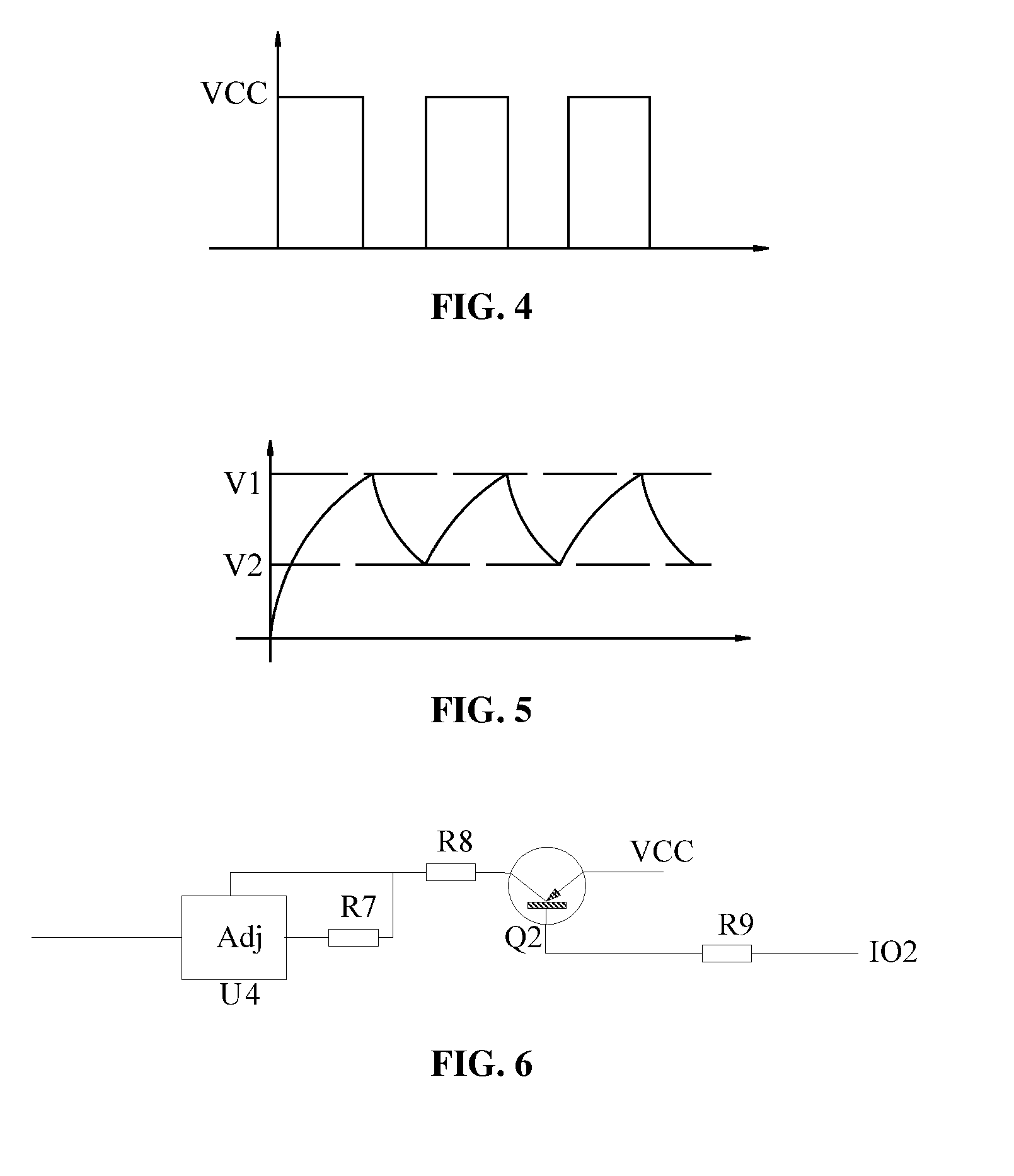
[0080]According to the embodiment of the present invention, an implementation of the humidity-sensitive capacitor heating unit is provided. As shown in FIG. 6, the function of heating the humidity-sensitive capacitor to prevent it from condensation in a high-humidity condition is realized, where a resistor R8 functions as the heating resistor.

[0081]When the ambient humidity measured by the microcontroller reaches a heating protection threshold, the microcontroller sets a pin IO2 (of the microcontroller) at low-level. At this point, a Bipolar junction transistor (BJT) Q2 is turned on, causing a constant current Ih to flow through a Vcc pin, the heating resistor R8, a resistor R7, a negative output voltage regulator U4 and then a RH terminal. The condensation prevention function for the humidity-sensitive capacitor is on, the humidity-sensitive capacitor is heated up, and a positive difference between humidity-sensitive capacitor surface temperature and ambient temperature is formed, ...

third embodiment

[0084]Corresponding to the implementation of the humidity-sensitive capacitor heating unit in the second embodiment, an implementation of the thermistor measuring unit is provided according to the embodiment of the present invention. As shown in FIG. 7, in cooperation with the humidity-sensitive capacitor heating unit, the thermistor measuring unit ensures normal operation of humidity measurement in high-humidity conditions.

[0085]As shown in FIG. 7, the microcontroller has a 12-bit Analog-to-Digital Converter (ADC) at a pin IO8, and a thermistor RT1 and a resistor R14 whose resistance is known are connected in series to form a voltage divider. When the resistance of RT1 is obtained, the temperature of RT1 can be calculated from it. The microcontroller also has a 12-bit ADC at a pin IO9, and a thermistor RT2 and a resistor R15 whose resistance is known are connected in series to form a voltage divider. When the resistance of RT2 is obtained, the temperature of RT2 can be calculated f...


PUM


Abstract

A humidity measurement device comprises a capacitance measurement unit (101) and a microcontroller (102). The capacitance measurement unit (101) is used to output a frequency signal of a humidity-sensitive capacitor (C1) by the humidity-sensitive capacitor (C1) and a frequency signal of a reference capacitor (C2) by the reference capacitor (C2) respectively. The microcontroller (102) is used to obtain a frequency value of the humidity-sensitive capacitor (C1) and a frequency value of the reference capacitor (C2) based on the frequency signal of the humidity-sensitive capacitor (C1) and the frequency signal of the reference capacitor (C2), and obtain a current ambient humidity value by using a linear function relationship of a frequency difference between the humidity-sensitive capacitor (C1) and the reference capacitor (C2) and a humidity value. A humidity measurement method includes using the said humidity measurement device to measure a current ambient humidity value.

Description

[0001]This application claims the benefit of Chinese patent application No. 200910243831.0, titled “Device for Humidity Measurement and Method thereof” and filed with the State Intellectual Property Office on Dec. 23, 2009, which is hereby incorporated by reference in its entirety.FIELD OF THE INVENTION[0002]The present invention relates to the field of measuring instrument, and in particular to a device for humidity measurement and a method thereof.BACKGROUND OF THE INVENTION[0003]Nowadays, humidity measurement has become an essential tool in environmental monitoring for HVAC (heating, ventilation, and air conditioning), communications base stations, building security, etc.[0004]Currently, commercially available electronic devices for humidity measurement used in environmental monitoring achieve the measurement, conversion and transmission of humidity by activating a humidity-sensitive element. Generally, the humidity-sensitive element may be capacitive, or resistive. In resistive ...

Claims


Application Information

Patent Timeline
IPC IPC(8): G01N27/22
CPCG01N27/228G01N27/223
Inventor FU, JUNCHANG, WEIYU, LIANBO
Owner BEIJING POLYMER SENSING TECH CO LTD
Learn More