Conductivity sensor assembly

Active Publication Date: 2012-10-11
CYTIVA SWEDEN AB
View PDF7 Cites 7 Cited by
  • Summary
  • Abstract
  • Description
  • Claims
  • Application Information

AI Technical Summary

Benefits of technology

[0014]According to the present invention, there is provided a new conductivity sensor cell design which can be used in association with piping diameters of process system sizes while keeping the same cell factor as for a smaller version conductivity cell, or even increasing it, without adding hold-up volume to the system.
[0015]This conductivity cell, or conductivity sensor assembly, which is defined in claim 1, is based on the concept of passing a portion of the liquid flow through a parallel flow channel where the conductivity measurement takes place. Thereby the cross-sectional area as well as the length of the cell are reduced, which thus reduces the hold-up volume of the flow or piping system in which the conductivity cell is mounted.
[0016]In a preferred embodiment, a pH flow-cell is integrated into the conductivity sensor assembly which will further reduce the hold-up volume of the liquid flow system.

Problems solved by technology

However, when scaling up a conductivity cell type designed for laboratory applications which has a certain cell factor, to the piping diameters used in process flows, keeping the same cell factor will considerably increase the length of the conductivity cell and result in undesired large hold-up volumes.
Conductivity cells of the prior art types mentioned above do not provide any solution to this problem.

Method used


Image

  • Conductivity sensor assembly
  • Conductivity sensor assembly
  • Conductivity sensor assembly

Examples


Embodiment Construction

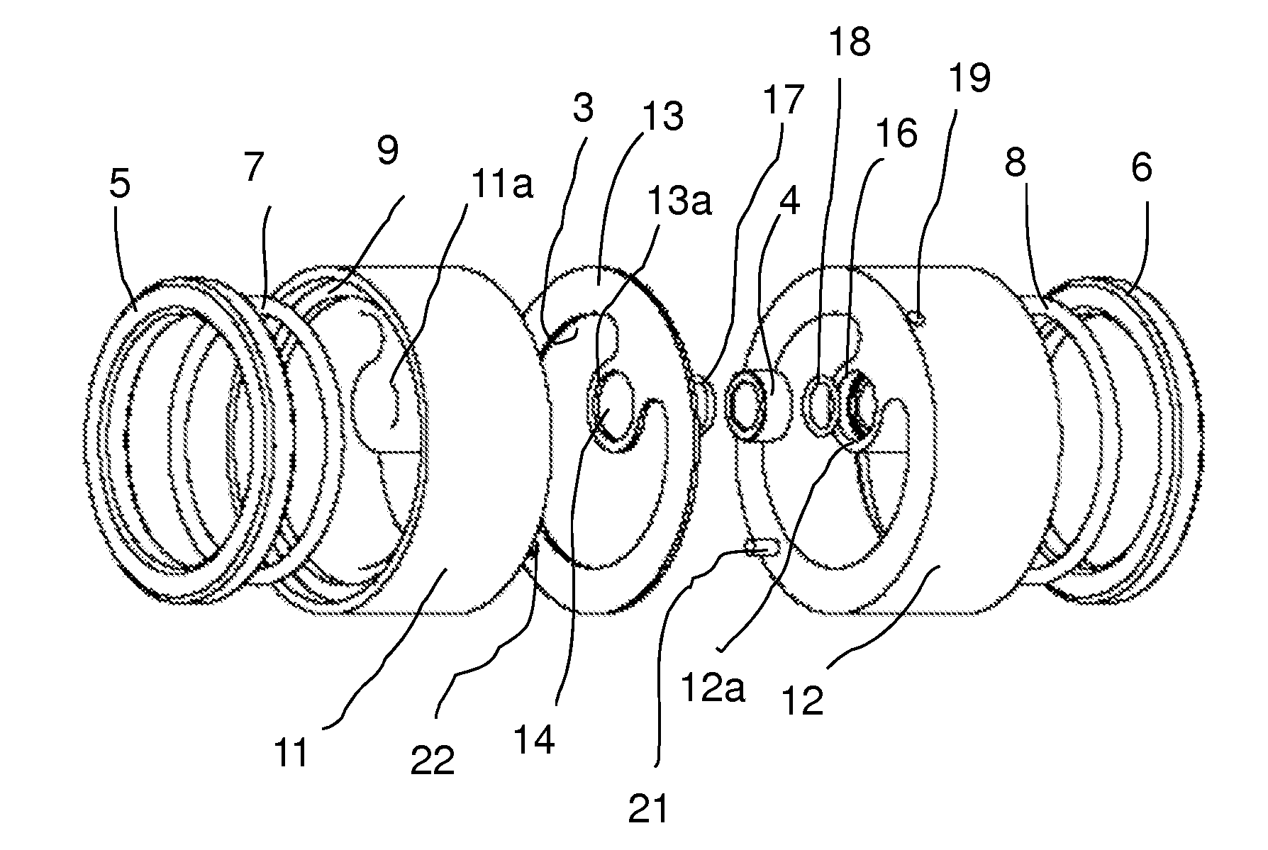
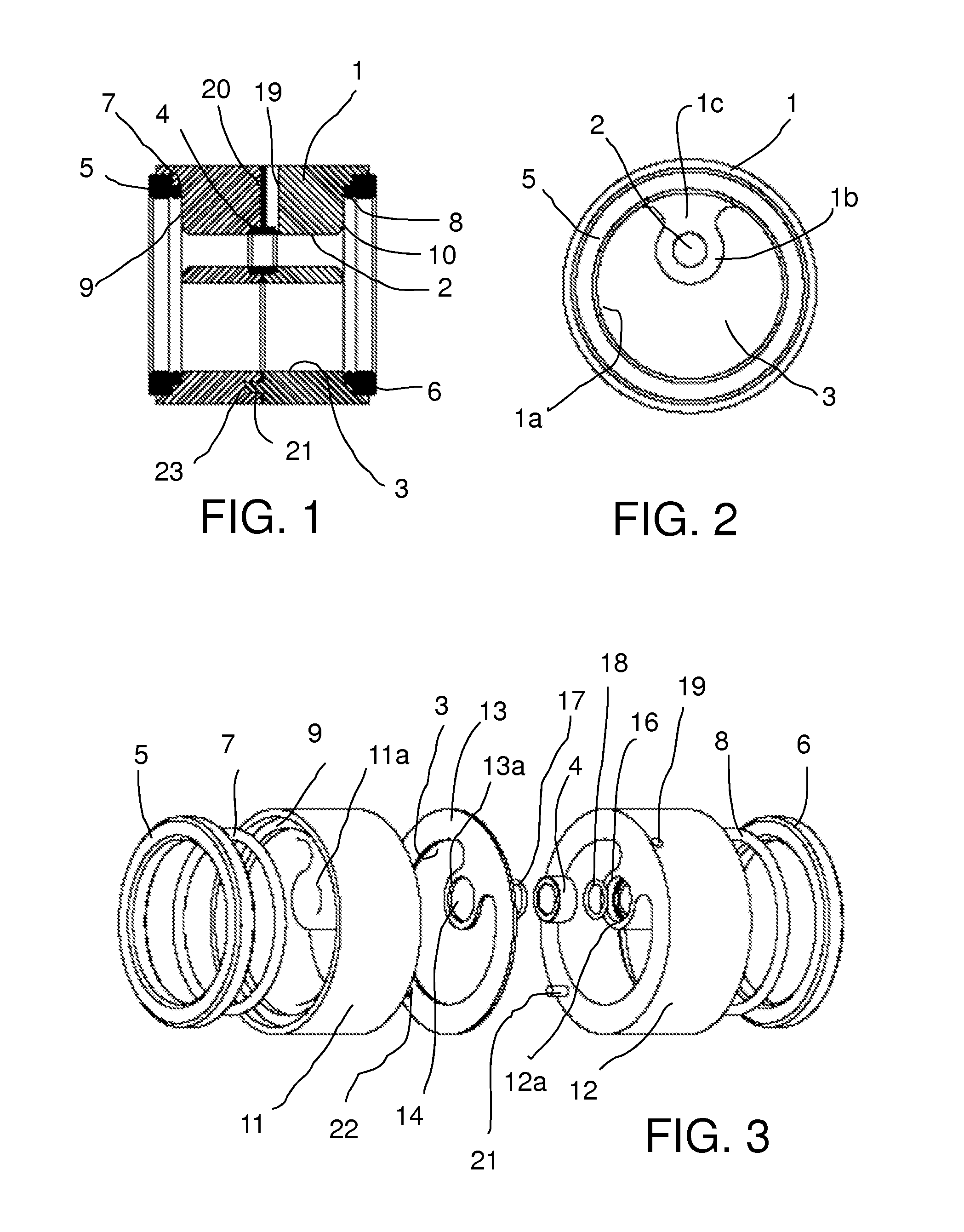
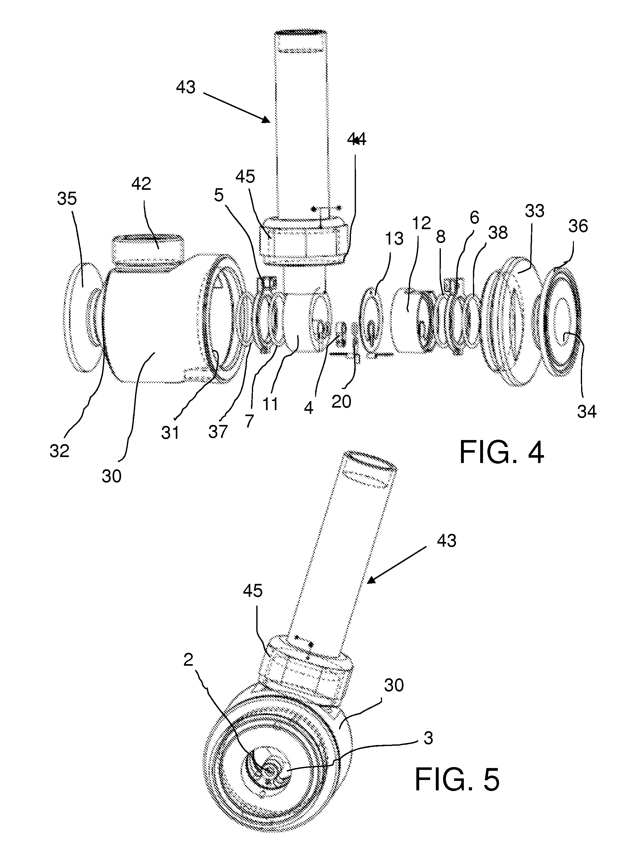
[0033]As mentioned above, the present invention is related to a flow-through type conductivity sensor, below frequently referred to as conductivity cell, for measuring the electrical conductivity of a liquid flow. The liquid flow is particularly a process flow, such as a chromatography column process flow or a cross-flow filtration process flow, where piping of relatively large dimensions are used and minimizing hold-up volumes is of importance.

[0034]The conductivity cell of the invention is of the type where conductivity is measured by applying an AC current between spaced electrodes in contact with the liquid. The electrodes are preferably circular, or annular, surrounding the liquid path. In such a cell, the “cell factor” (which is constant for a given cell) is the “distance between electrodes” divided by the “cross sectional area of the current”, i.e. the cross sectional area of the liquid flow.

[0035]Assume that a certain conductivity cell of this type has a length of 10 cm and ...


PUM


Abstract

A flow-through conductivity sensor assembly comprises a housing (4) having a flow passage with an inlet end and an outlet end. The cross section of at least a section of the flow passage extension between the inlet and outlet ends is divided into a conductivity measuring channel (2) and a parallel by-pass channel (3) of larger cross-sectional area than the measuring channel (2).

Description

FIELD OF THE INVENTION[0001]The present invention relates to measurement of conductivity, and more particularly to a sensor assembly for measuring the conductivity of a flowing liquid.BACKGROUND OF THE INVENTION[0002]Conductivity, or electrolytic conductivity, is defined as the ability of a substance to conduct electrical current. Conductivity is the reciprocal of resistivity, and its basic unit is siemens per meter (S / m). For a liquid, the conductivity is a summation of contributions from all ions present in the liquid.[0003]The measurement of the conductivity of liquids is usually performed in a so-called conductivity cell. Conductivity cells can be classified according to the technique by which they interact with the sample and also by the geometry of the cell design. The two operating techniques used are the contacting technique, and the inductive or toroidal technique. In both cases, an AC electrical input signal is applied to the conductivity cell, and the resultant AC electri...

Claims


Application Information

Patent Timeline
IPC IPC(8): G01R27/28
CPCG01N27/07G01R27/22G01N2030/645G01N27/08
Inventor ANDERSSON, LARSD'ARGY, STEFANFRICKING, PATRICTOLLSTOY, JOACHIM
Owner CYTIVA SWEDEN AB
Why Eureka
Try Eureka