Ultrasound guided positioning of cardiac replacement valves with 3D visualization

a technology of cardiac replacement valves and ultrasound guided positioning, which is applied in the direction of instruments, catheters, applications, etc., can solve the problems of difficult to determine the exact position of the valve with respect to the relevant anatomy, difficult to visualize the valve and its deployment catheter, and difficult to clearly see and differentiate the tissu

Inactive Publication Date: 2012-10-11
IMACOR INC
View PDF0 Cites 37 Cited by
  • Summary
  • Abstract
  • Description
  • Claims
  • Application Information

AI Technical Summary

Problems solved by technology

It is easy to see the tissue and the anatomical landmarks on the ultrasound image, but difficult to visualize the valve and its deployment catheter.
Conversely, it is easy to see the valve and catheter on the fluoroscopy image, but difficult to clearly see and differentiate the tissue.
Since neither imaging modality provides a clear view of both the anatomy and the valve, it difficult to determine exactly where the valve is with respect to the relevant anatomy.
This makes positioning of the artificial valve prior to deployment quite challenging.

Method used


Image

  • Ultrasound guided positioning of cardiac replacement valves with 3D visualization
  • Ultrasound guided positioning of cardiac replacement valves with 3D visualization
  • Ultrasound guided positioning of cardiac replacement valves with 3D visualization

Examples


Embodiment Construction

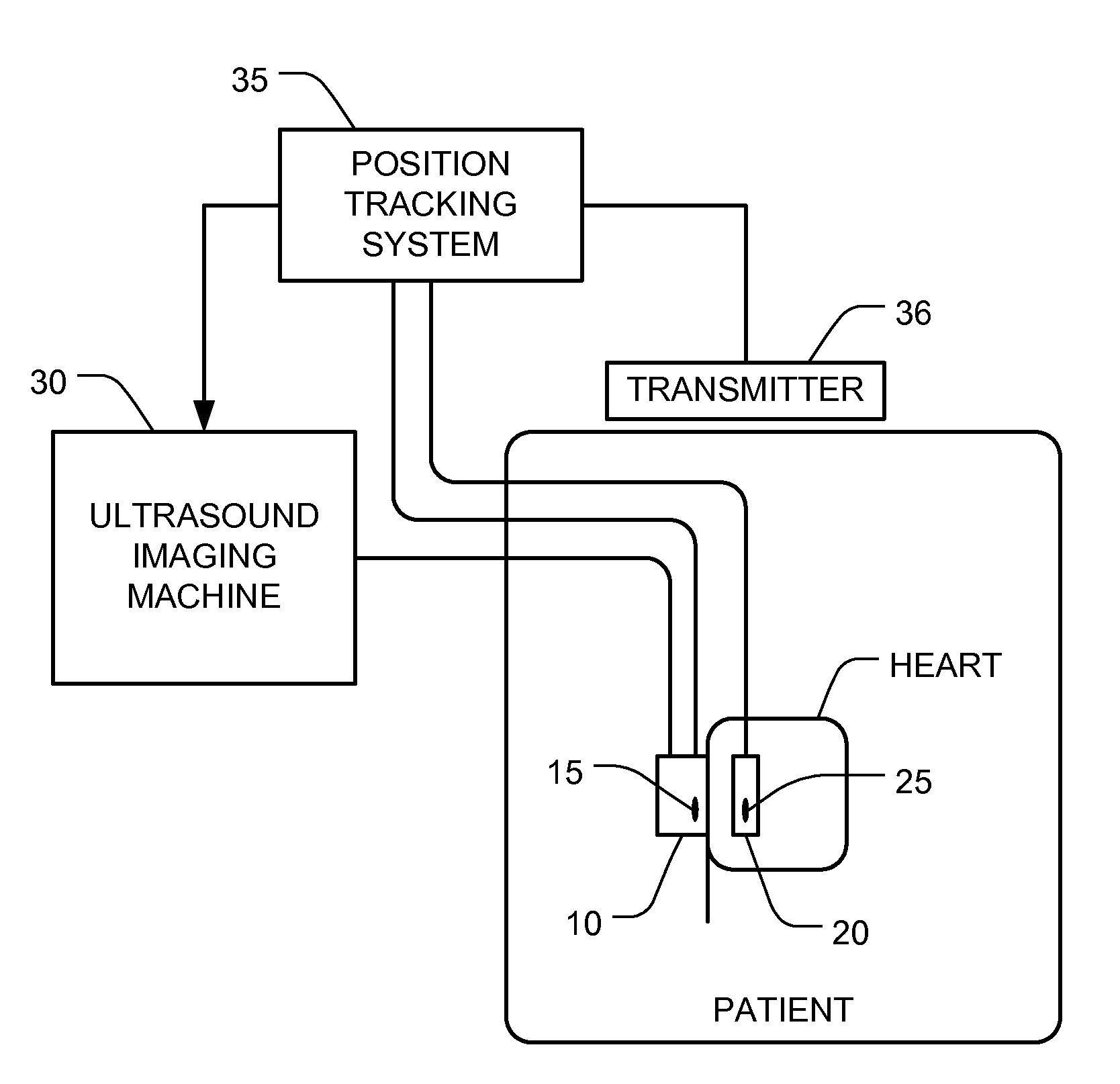
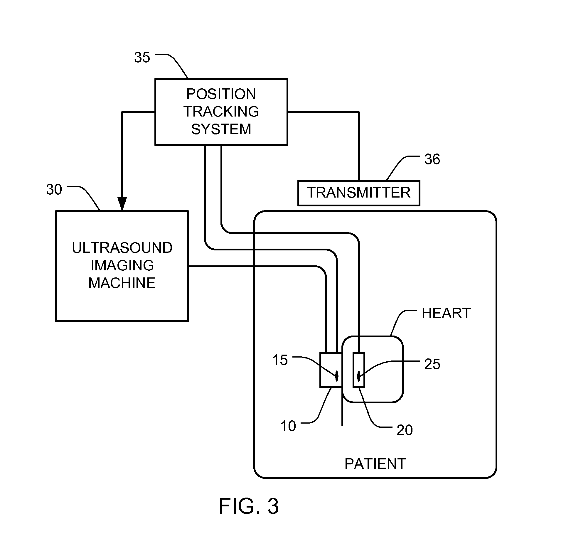
[0016]FIGS. 1-4 depict one embodiment of the invention in which the position of the valve may be visualized easily on the ultrasound image so as to make the deployment of the valve much easier due to a much more confident assessment of its position. In this embodiment, position sensors are added to a conventional ultrasound probe and to a conventional valve delivery apparatus, and data from those position sensors is used to determine the location of valve with respect to the relevant anatomy.

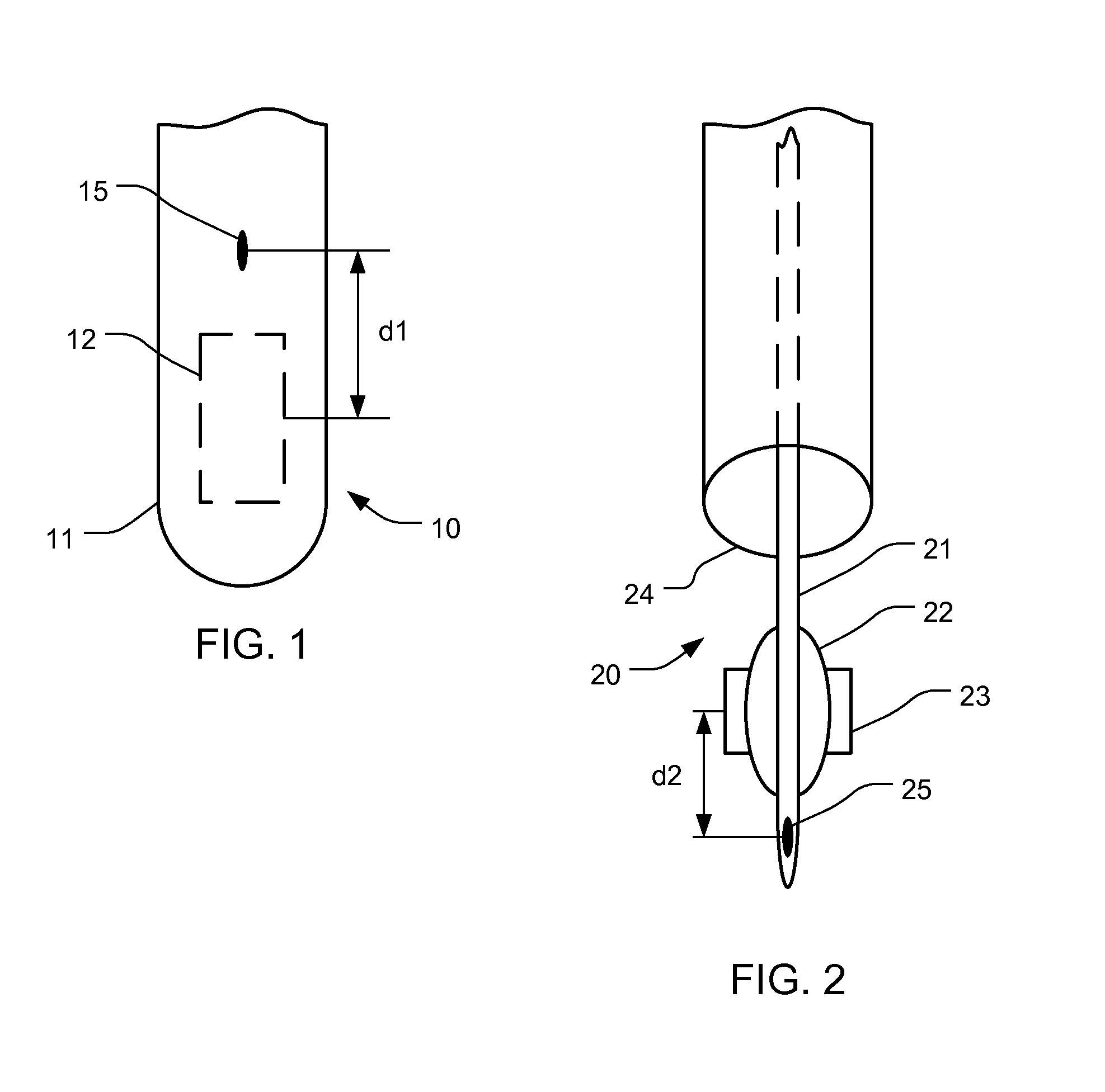
[0017]FIG. 1 depicts the distal end of an ultrasound probe 10. In most respects, the ultrasound probe 10 is conventional—it has a housing 11 and an ultrasound transducer 12 located within the distal end of the probe 10 and a flexible shaft (not shown). However, in addition to the conventional components, a position sensor 15 is added, together with associated wiring to interface with the position sensor 15. The position sensor 15 can be located anywhere on the distal end of the probe 10, as long...


PUM


Abstract

A device (e.g., a valve) can be visualized in a patient's body (e.g., in the patient's heart) using an ultrasound system with added position sensors. One position sensor is mounted in the ultrasound probe, and another position sensor is mounted in the device installation apparatus. The device's position with respect to the imaging plane is determined based on the detected positions of the position sensors and known geometric relationships. A representation of the device and the imaging plane, as viewed from a first perspective, is displayed. The perspective is varied to a second perspective, and a representation of the device and the imaging plane, as viewed from the second perspective, is displayed. Displaying the device and the imaging plane from different perspectives helps the user visualize where the device is with respect to the relevant anatomy.

Description

CROSS REFERENCE TO RELATED APPLICATIONS[0001]This Application claims the benefit of U.S. Provisional Application 61 / 474,028, filed Apr. 11, 2011, and U.S. Provisional Application 61 / 565,766, filed Dec. 1, 2011, each of which is incorporated herein by reference.BACKGROUND[0002]Conventional percutaneous cardiac valve replacement procedure relies on Trans-Esophageal Echocardiography (TEE) in combination with Fluoroscopy for guiding the valve into position where it is to be deployed. It is easy to see the tissue and the anatomical landmarks on the ultrasound image, but difficult to visualize the valve and its deployment catheter. Conversely, it is easy to see the valve and catheter on the fluoroscopy image, but difficult to clearly see and differentiate the tissue. Since neither imaging modality provides a clear view of both the anatomy and the valve, it difficult to determine exactly where the valve is with respect to the relevant anatomy. This makes positioning of the artificial valve...

Claims


Application Information

Patent Timeline
Patent Type & Authority Applications(United States)
IPC IPC(8): A61B8/00
CPCA61B6/12A61B8/52A61B8/12A61B8/4254A61B8/4488A61B8/466A61B8/467A61B19/5244A61F2/2427A61B2019/5263A61B2019/5276A61B2019/5278A61B5/055G01N29/00A61B8/13A61B8/461A61B8/4444A61B8/0841A61B2034/2063A61B2090/3782A61B34/20A61B2090/378
Inventor HARHEN, EDWARD P.HERON, NICOLAS
Owner IMACOR INC
Why Eureka
Try Eureka