
Laser module

Inactive Publication Date: 2012-10-18
MITSUBISHI ELECTRIC CORP
View PDF6 Cites 8 Cited by
  • Summary
  • Abstract
  • Description
  • Claims
  • Application Information

AI Technical Summary

Benefits of technology

[0012]According to the invention, it becomes possible to obtain an inexpensive laser module by lowering stress applied to the LD array.

Problems solved by technology

As the device size increases, stress intensification occurs when the LD array is mounted or driven due to a mismatch of linear expansion coefficients between the device and a joined member.
Also, when a device temperature is high, development of the defect is accelerated and consequently a device life is shortened.

Method used


Image

  • Laser module
  • Laser module
  • Laser module

Examples


first embodiment

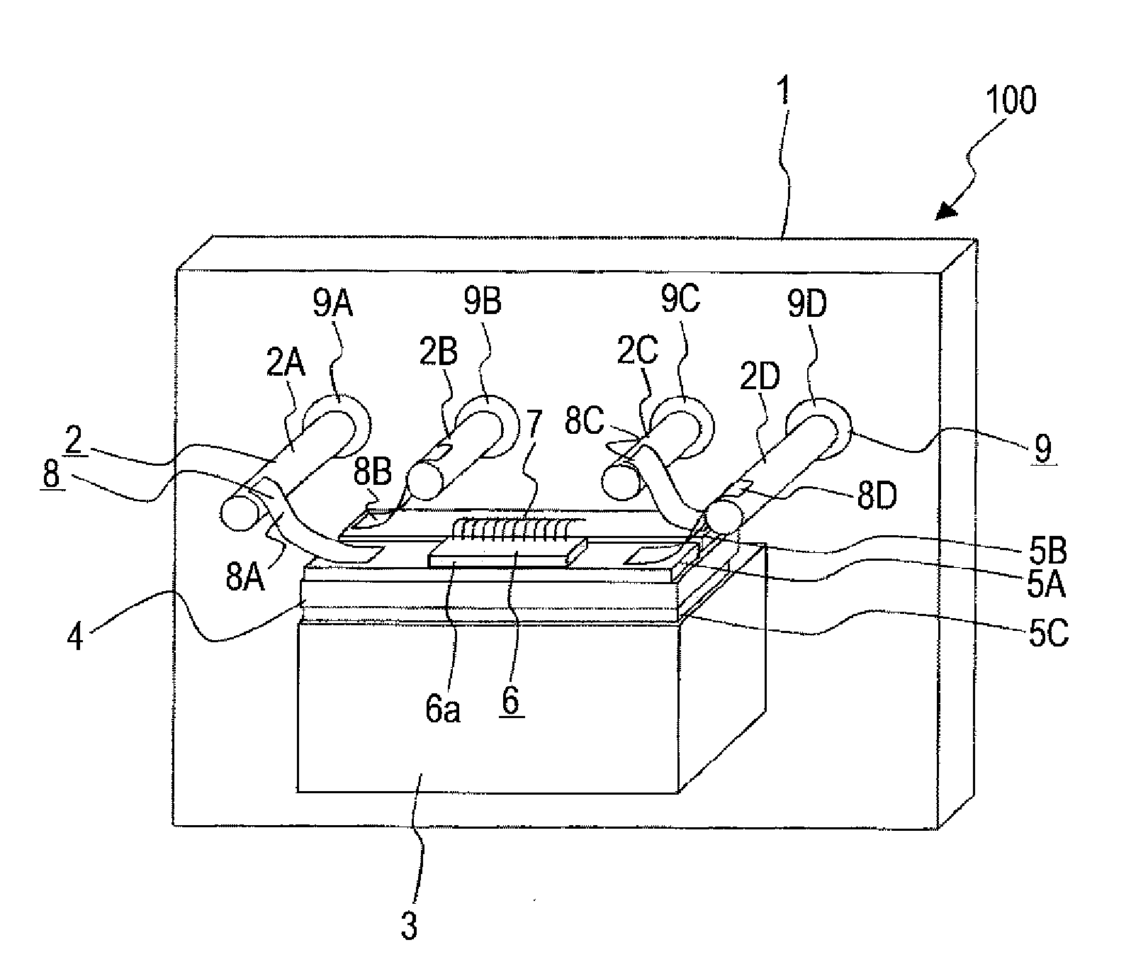
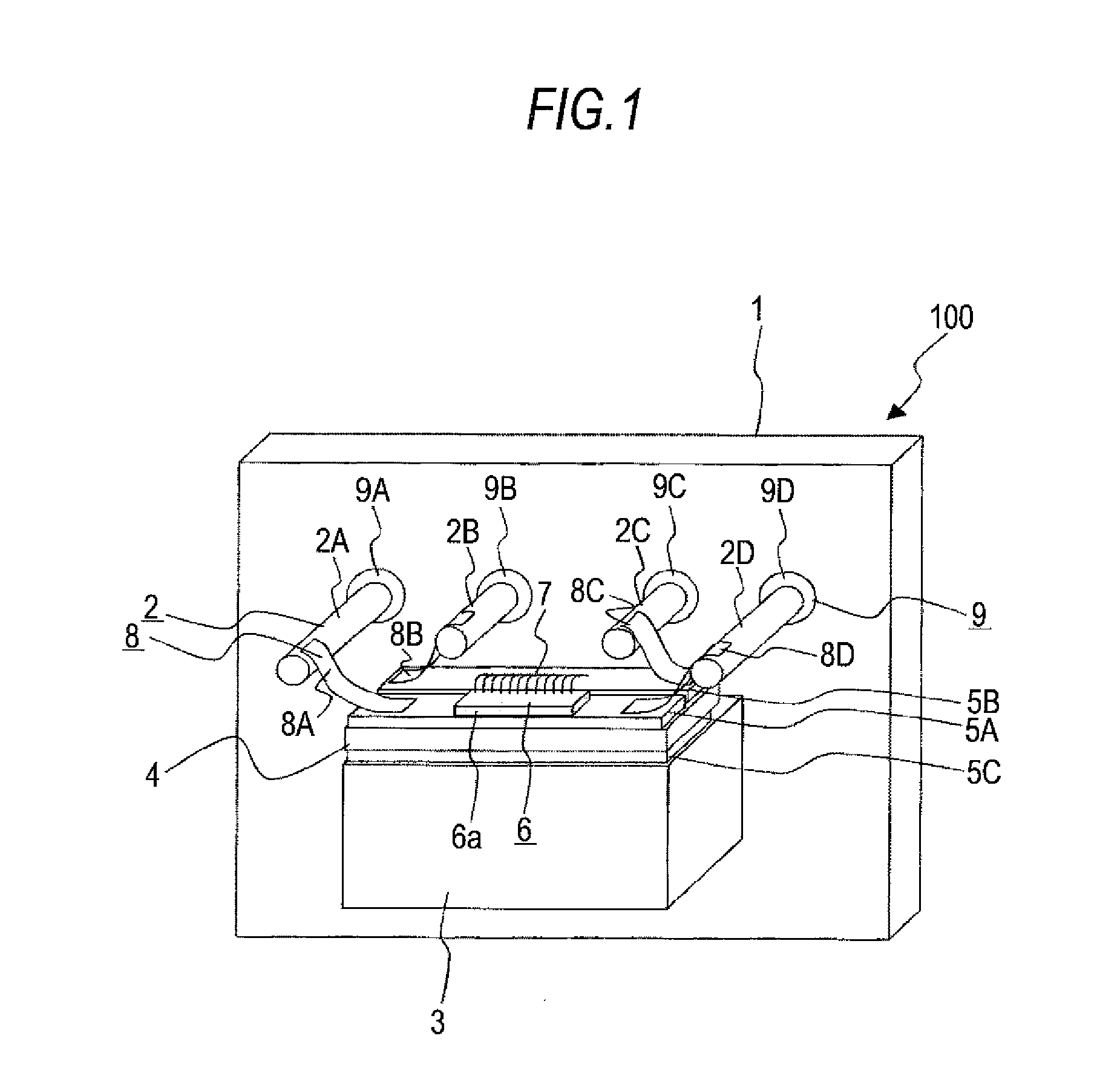
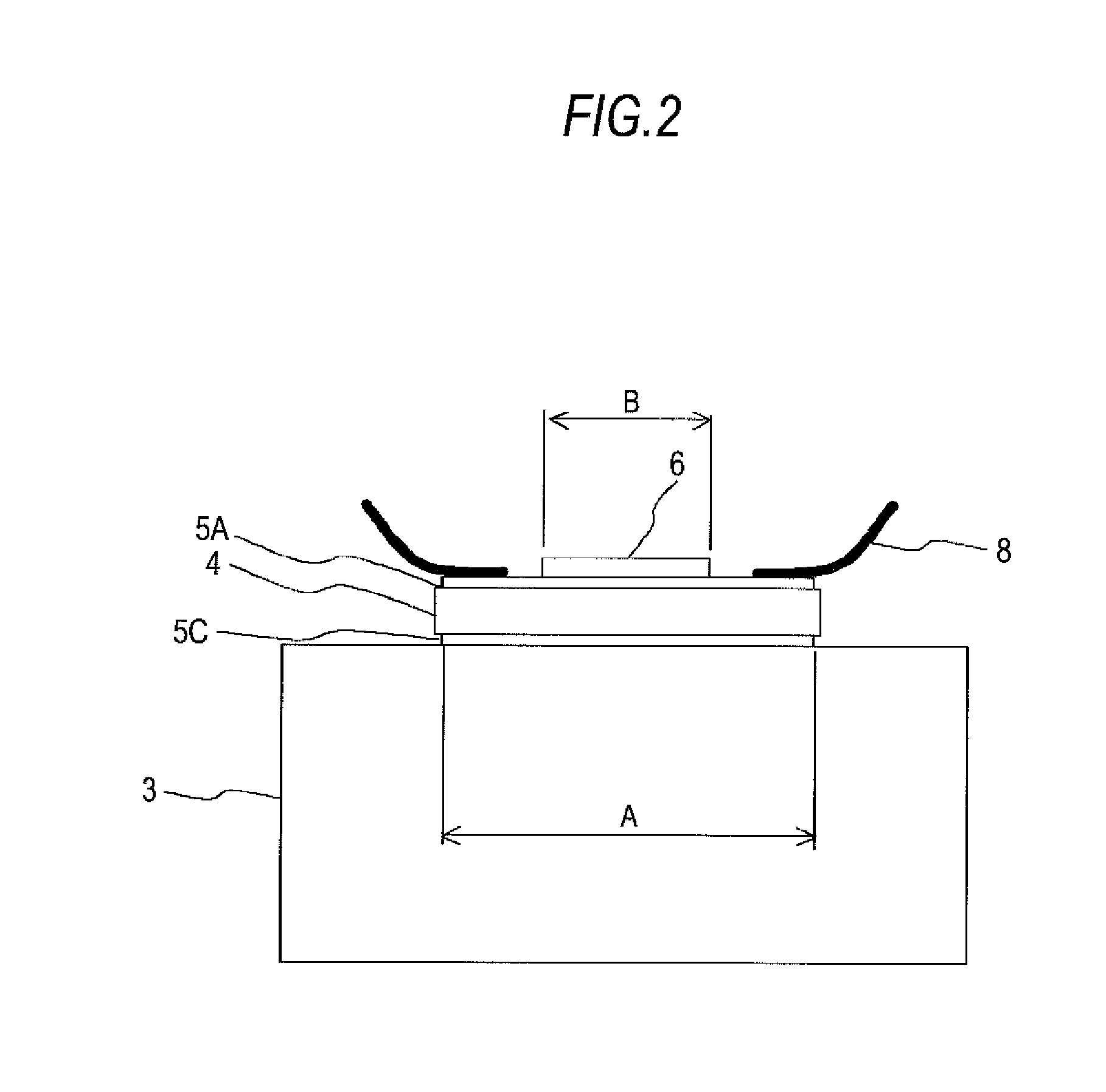
[0022]Hereinafter, a structure of a laser module 100 according to this embodiment of the invention will be described using FIG. 1 through FIG. 3. FIG. 1 is a perspective view of the laser module 100 of this embodiment. FIG. 2 is a front view of the laser module 100 of this embodiment. FIG. 3 is a side view of the laser module 100 of this embodiment. Herein, a side of the laser module 100 from which a laser beam is emitted is defined as the front surface.

[0023]The laser module 100 is formed of a stem 1, a lead pin 2, a heat sink 3, a sub-mount substrate 4 having plated layers 5A, 53, and 5C, an LD array 6, a wire interconnection 7, and a ribbon interconnection 8.

[0024]A stem 1 is a plate-like member made of a metal material, such as Fe, and provided with four openings through which lead pins 2A through 2D are inserted.

[0025]The lead pins 2A through 2D are made of a conductive material and serve as feeding wires that supply the LD array 6 with power from an unillustrated power supply....


PUM


Abstract

A laser module includes: a heat sink that releases heat from a member in contact with the heat sink; a sub-mount substrate that is disposed on the heat sink and made of an insulating material; a feeding layer that is disposed on the sub-mount substrate; and a laser diode array that has plural light-emitting portions disposed on the feeding layer in a parallel arrangement. A linear expansion coefficient of the sub-mount substrate is made smaller than a linear expansion coefficient of the laser diode array, and the linear expansion coefficient of the sub-mount substrate in a state connected to the heat sink having a larger linear expansion coefficient than the laser diode array is set to fall within a predetermined range including the linear expansion coefficient of the laser diode array.

Description

TECHNICAL FIELD[0001]The present invention relates to a laser module using a laser diode array device.BACKGROUND ART[0002]Recently, there has been an increasing need of a higher output of a laser diode (LD) used for processing or as a light source. As a technique of increasing an output of the LD, there is a method using a laser diode array device (hereinafter, referred to as the LD array) in which plural light-emitting spots (emitters) are arrayed in a parallel arrangement within a single chip.[0003]The LD array is substantially equivalent to dispose plural devices each having one light-emitting spot in a parallel arrangement. Accordingly, both a device size and a gross heating value increase with an increasing number of emitters disposed in a parallel arrangement. As the device size increases, stress intensification occurs when the LD array is mounted or driven due to a mismatch of linear expansion coefficients between the device and a joined member. Then, there occurs a phenomeno...

Claims


Application Information

Patent Timeline
IPC IPC(8): H01S3/04
CPCH01S5/02272H01S5/02276H01S5/02476H01S5/4031H01L2224/48091H01L2924/00014H01S5/0237H01S5/02345H01L2021/26573
Inventor TAMAYA, MOTOAKINANBA, CHISEYANAGISAWA, TAKAYUKIOE, SHINICHIYAMAMOTO, SHUHEIYOKOYAMA, AKIRA
Owner MITSUBISHI ELECTRIC CORP
Features
  • Generate Ideas
  • Intellectual Property
  • Life Sciences
  • Materials
  • Tech Scout
  • Unparalleled Data Quality
  • Higher Quality Content
  • 60% Fewer Hallucinations
Learn More