System and method for controlling crop transfer

a technology of crop transfer and system, applied in the direction of loading/unloading, storage devices, mowers, etc., can solve the problems of system not taking into account and manual orientation of the transfer device, and achieve the effect of reducing the number of inputs

Inactive Publication Date: 2012-10-18
CLAAS SELBSTFAHRENDE ERNTEMASCHINEN GMBH
View PDF10 Cites 65 Cited by
  • Summary
  • Abstract
  • Description
  • Claims
  • Application Information

AI Technical Summary

Benefits of technology

[0009]In one embodiment, the invention provides a system and method for the automatic control of the crop transfer, which provide the drivers of a hauling vehicle and a harvesting machine with greater relief from observing the transfer procedure. Furthermore, a corresponding method will be provided.
[0010]In the inventive system, a control unit, which controls the actuators of the transfer device and, therefore, the orientation of the crop discharge flow, can be operated to generate a control signal for the hauling vehicle that specifies a position of the hauling vehicle relative to the harvesting machine that is suitable for transfer into the loading container. System operation is based on the finding that two processes must interact dynamically in a suitable manner to ensure loss-free, automatic control of the procedure for filling the loading container. The first of the two processes is the orientation of the crop discharge flow which can be influenced quickly by actuating the actuators of the transfer device.
[0011]Simultaneously, the loading container must be located in a suitable position relative to the harvesting machine, i.e., the second process. This second process has a much longer reaction time compared to the orientation of the crop discharge flow. Since the control unit—which directs the crop discharge flow within the design-related boundaries of the loading container by orienting the transfer device—also generates a control signal directed to the hauling vehicle that specifies a relative position of the hauling vehicle that is suitable for transfer into the loading container, the inventive system advantageously provides the drivers of the hauling vehicle and the harvesting machine with greater relief from observing the transfer procedure and links the two processes to each other in a favorable manner to prevent transfer losses and relieve the driver.
[0012]In an embodiment, the control signal can be output in a form that can be perceived by a driver of the hauling vehicle. For example, a control instruction could be output in a display that is visible to the driver of the hauling vehicle. The output could also be delivered acoustically by way of a loudspeaker. This could be a ground speed requirement and / or a direction-of-steering indicator. Such a signal output to the driver offers the advantage that the driver receives supportive, precise driving instructions—while allowing him to freely decide whether—or to what extent—to follow this instruction.
[0013]To increase comfort and relieve the driver further, the control signal is preferably input into a ground speed regulator assigned to the hauling vehicle, which automatically positions the hauling vehicle relative to the harvesting machine. By way of this measure, the ground speed of the hauling vehicle is controlled in a manner that is adapted to the transfer procedure and is partially autonomous or fully autonomous, depending on the extent of implementation, with the result that the self-propelled harvesting machine, as the leading vehicle, also controls the hauling vehicle.

Problems solved by technology

Due to high ground speeds on the field, manual orientation of the transfer device requires much effort on the part of the driver of a forage harvester.
In addition, the system does not account for the fact that the position of the loading container relative to the harvesting machine that is optimal for the transfer procedure—depending on the filling state of the loading container, for example—can change entirely during the filling procedure.

Method used


Image

  • System and method for controlling crop transfer
  • System and method for controlling crop transfer
  • System and method for controlling crop transfer

Examples


Embodiment Construction

[0031]The following is a detailed description of example embodiments of the invention depicted in the accompanying drawings. The example embodiments are presented in such detail as to clearly communicate the invention and are designed to make such embodiments obvious to a person of ordinary skill in the art. However, the amount of detail offered is not intended to limit the anticipated variations of embodiments; on the contrary, the intention is to cover all modifications, equivalents, and alternatives falling within the spirit and scope of the present invention, as defined by the appended claims.

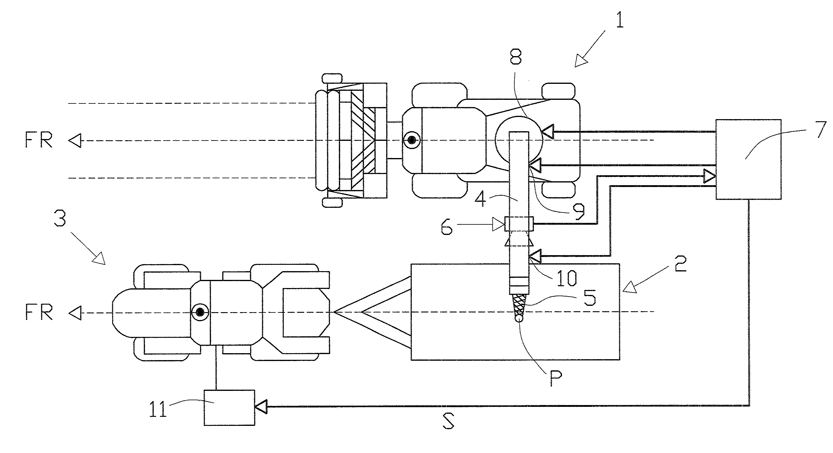
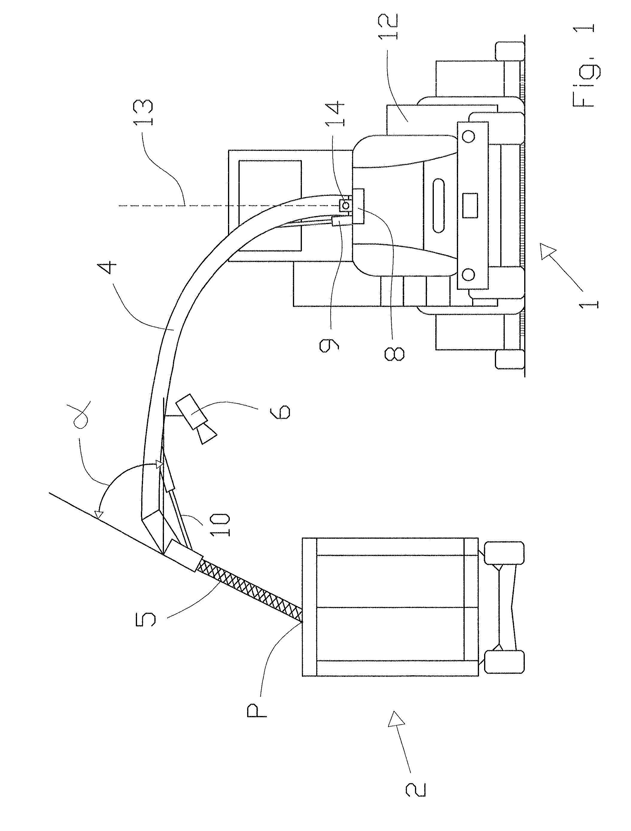
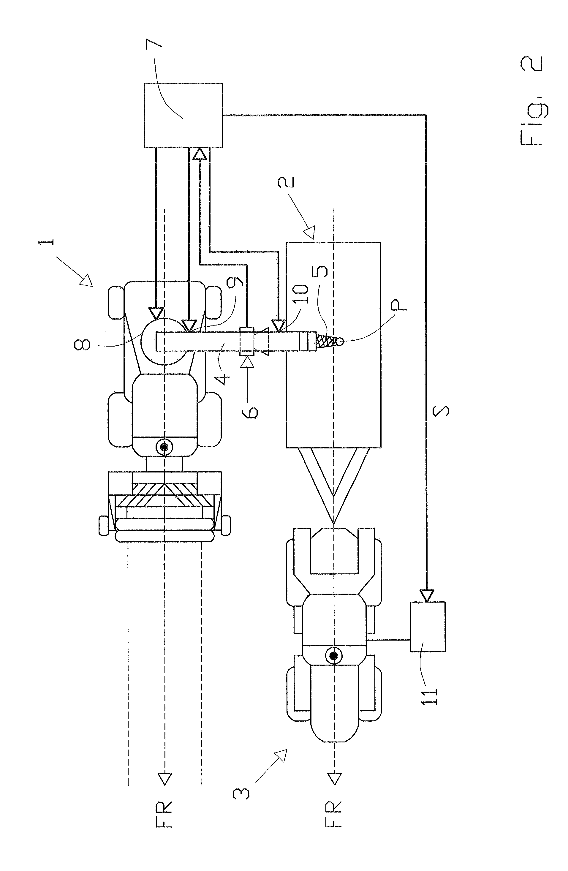
[0032]FIG. 1 shows, in a schematic view from the rear, a self-propelled forage harvester 1, which hurls (transfers) harvested and processed crop by way of an upper discharge chute 4 in the form of a crop discharge flow into a loading container 2 located next to the forage harvester 1. The loading container 2 is mounted on a driveable frame and is drawn parallel to the direction of travel of...


PUM


Abstract

A system for controlling crop transfer from a self-propelled agricultural harvesting machine into the loading container of a hauling vehicle includes a transfer device assigned to the harvesting machine from which the crop emerges in the form of a crop discharge flow and a detection device which detects the position of the loading container relative to the harvesting machine and transmits it to a control unit. The control unit actuates at least one actuator assigned to the transfer device in such a way that the crop discharge flow lands within the loading container in order to fill it with crop. The control unit generates a control signal (S) for the hauling vehicle that specifies a position of the hauling vehicle relative to the harvesting machine that is suitable for transfer into the loading container.

Description

CROSS-REFERENCE TO A RELATED APPLICATION[0001]The invention described and claimed hereinbelow is also described in German Patent Application DE 10 2011 002 071.3, filed on Apr. 15, 2011. The German Patent Application, whose subject matter is incorporated by reference herein, provides the basis for a claim of priority of invention under 35 U.S.C. 119(a)-(d).BACKGROUND OF THE INVENTION[0002]The invention relates to a system for controlling crop transfer from a self-propelled agricultural harvesting machine into a loading container of a hauling vehicle, comprising a transfer device assigned to the harvesting machine, from which the crop emerges in the form of a crop discharge flow, and a detection device which ascertains a position of the loading container relative to the harvesting machine and transfers the position to a control unit, wherein the control unit actuates at least one actuator assigned to the transfer device in such a way that the crop discharge flow lands within the load...

Claims


Application Information

Patent Timeline
Patent Type & Authority Applications(United States)
IPC IPC(8): B65G67/22
CPCA01D43/087
Inventor DIEKHANS, NORBERTHUSTER, JOCHENCLAUSSEN, FRANK
Owner CLAAS SELBSTFAHRENDE ERNTEMASCHINEN GMBH
Why Eureka
Try Eureka