
Composite steel part and manufacturing method for the same

Active Publication Date: 2012-10-25
AISIN AW CO LTD
View PDF0 Cites 11 Cited by
  • Summary
  • Abstract
  • Description
  • Claims
  • Application Information

AI Technical Summary

Benefits of technology

[0009]The present invention has been made against such background, and has an object to provide a manufacturing method for a composite steel part that can achieve a sufficient effect of improving the surface hardness of a part that requires wear resistance, that can improve the characteristics of a welded portion more than ever, and that can completely abolish an anti-carburizing process during manufacture.
[0018]The composite steel part according to the above second aspect can be easily manufactured by applying the above manufacturing method, for example. The cylindrical portion formed by the carburized quenched portion having the above specific structure demonstrates excellent wear resistance, and the welded portion of the above flange portion having the specific structure provides excellent characteristics.

Problems solved by technology

The anti-carburizing process and the anti-carburizing agent removal process involve a significantly large number of man-hours to result in a cost increase.
In the case where the anti-carburizing process is omitted, on the other hand, the amount of carbon in the raw material of the welding expected portion may be increased to disadvantageously cause a weld crack during welding.
However, it is difficult to significantly increase the carbon content from the viewpoint of workability, and the carbon concentration on the surface may not be made so high as in the case where carburization is performed.
Therefore, the hardness improving effect of the quenching is low, and desired wear resistance may not be obtained.

Method used


Image

  • Composite steel part and manufacturing method for the same
  • Composite steel part and manufacturing method for the same
  • Composite steel part and manufacturing method for the same

Examples


embodiment

First Embodiment

[0039]The composite steel part and the manufacturing method for the composite steel part described above according to an embodiment will be described with reference to the drawings.

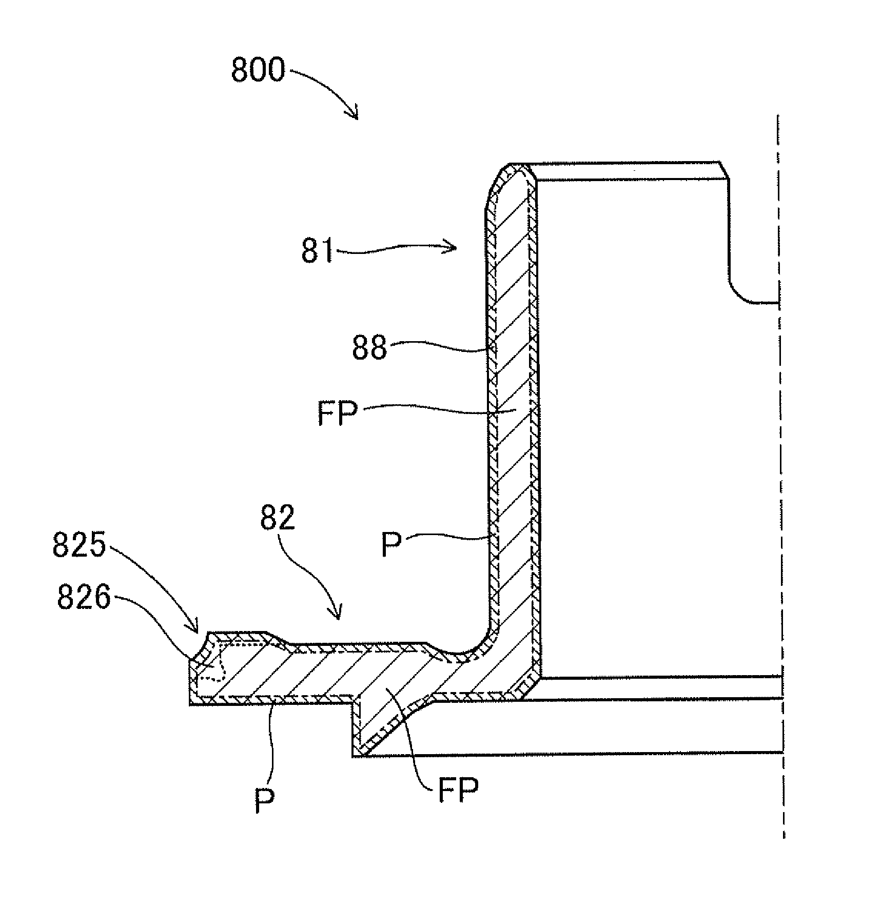
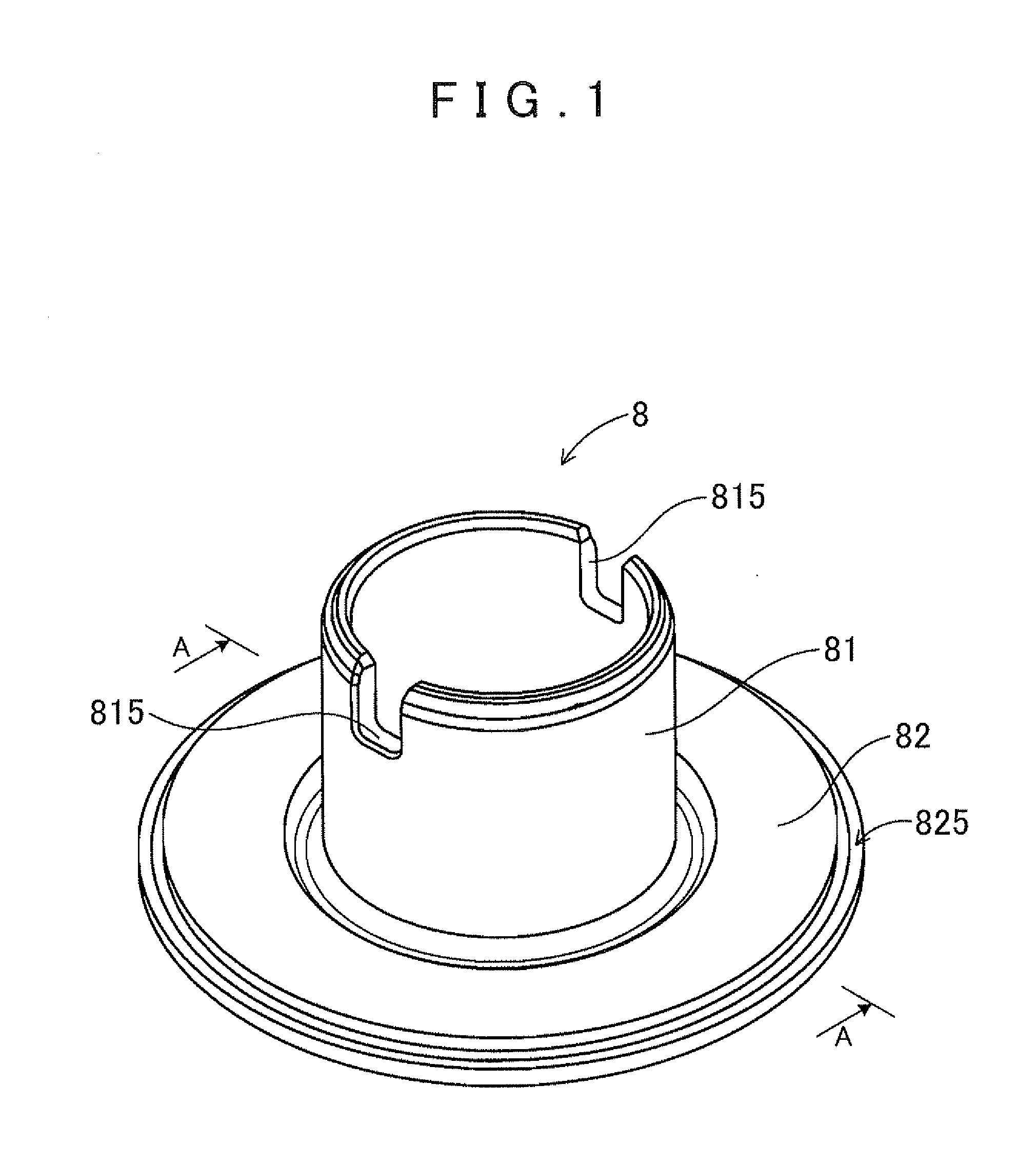
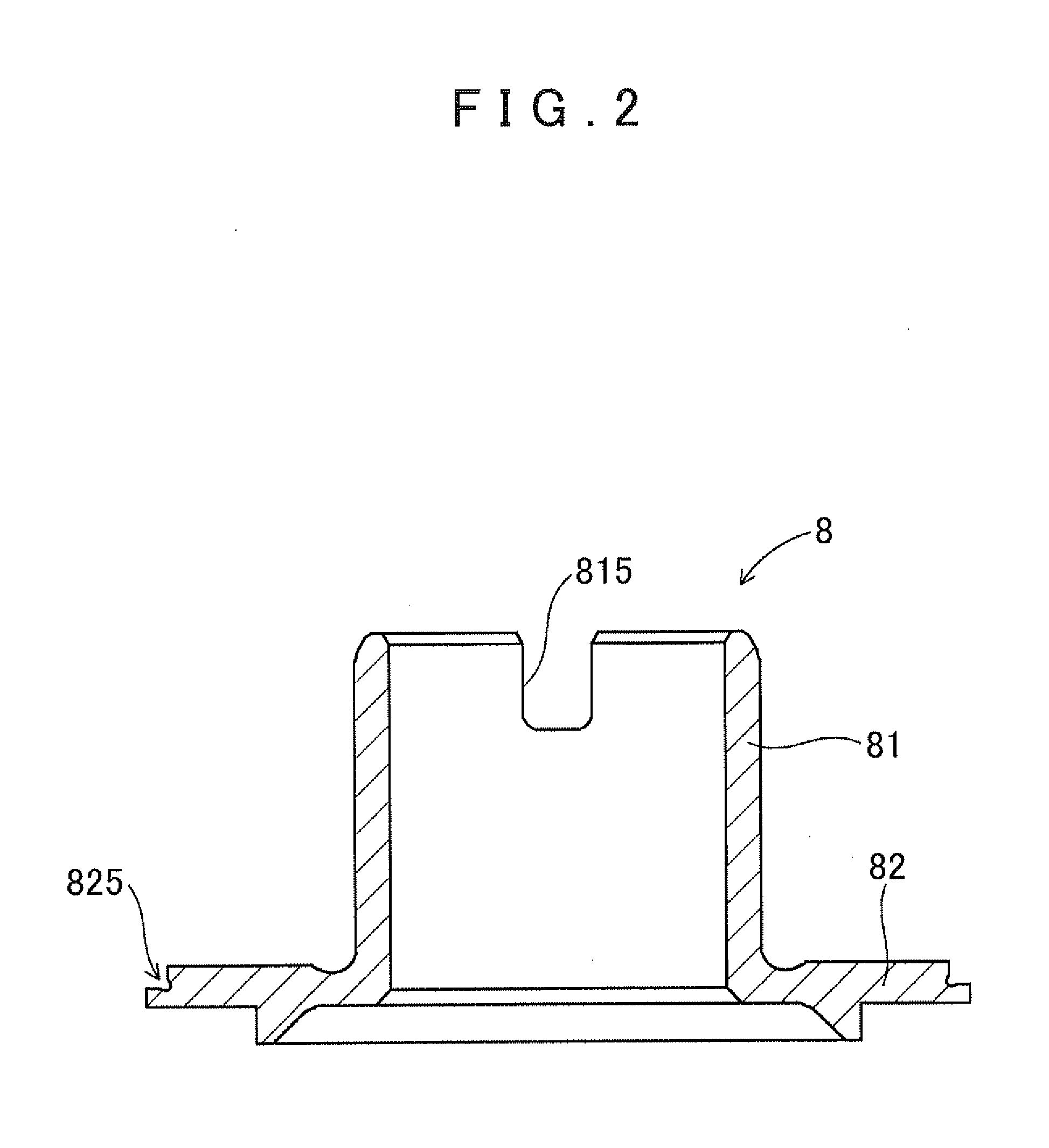
[0040]As shown in FIGS. 1 and 2, a first steel part 8 manufactured in the embodiment is a steel part to be incorporated in an automotive automatic transmission and including a cylindrical portion 81 formed in a cylindrical shape and a flange portion 82 provided to extend radially outward from one end of the cylindrical portion 81. In the first steel part 8, the cylindrical portion 81 is a carburized quenched portion which has been subjected to a carburizing quenching hardening process, and the flange portion 82 includes a welding expected portion 825 to be welded to a second steel part. The other end of the above cylindrical portion 81 is provided with two notched portions 815 arranged in the circumferential direction.

[0041]In order to manufacture such a first steel part 8, first, an inter...


PUM

PropertyMeasurementUnit
Concentrationaaaaaaaaaa

Abstract

A manufacturing method for a composite steel part including preparing an intermediate product in which an extra portion, which has a thickness equal to or more than that of a carburized layer to be formed in a subsequent carburizing step, has been added to a welding expected portion, carburizing the intermediate product by heating to an austenitizing temperature or more in a carburizing atmosphere, then cooling the intermediate product at a cooling rate less than a rate at which martensitic transformation occurs and without completing structural transformation due to the cooling, quenching a portion of the intermediate product after heating to an austenitizing range by high-density energy and thereafter cooling to cause martensitic transformation to form a carburized quenched portion, removing an extra portion of the intermediate product; and then welding a second steel part to the welding expected portion.

Description

INCORPORATION BY REFERENCE[0001]The disclosure of Japanese Patent Application No. 2011-096433 filed on Apr. 22, 2011 including the specification, drawings and abstract is incorporated herein by reference in its entirety.BACKGROUND OF THE INVENTION[0002]The present invention relates to a composite steel part including both a carburized quenched portion and a welded portion, and to a manufacturing method for the composite steel part.DESCRIPTION OF THE RELATED ART[0003]A part called a sleeve pump impeller extension is an example of steel parts to be incorporated in an automotive automatic transmission. The steel part is, as it were, a composite steel part fabricated by welding a first steel part, which includes a cylindrical portion formed in a cylindrical shape and a flange portion provided to extend radially outward from one end of the cylindrical portion, and a second steel part to each other at the flange portion. The outer peripheral surface of the cylindrical portion of the first...

Claims


Application Information

Patent Timeline
IPC IPC(8): C23C8/20B32B15/04
CPCC23C8/02C23C8/20C23C8/22C23C8/80C21D2211/009C21D1/25C21D2211/002C21D2211/008C21D1/06
Inventor OBAYASHI, KOJITAKEUCHI, MAMORUSUGIYAMA, RYUTASHIMIZU, KENKATO, KOICHI
Owner AISIN AW CO LTD
Learn More