Touch-screen device including tactile feedback actuator

a technology of tactile feedback and touch screen, applied in the field of touch screen devices, can solve the problems of increased data entry error rates, decreased user satisfaction, and insufficient transparency of pressurized fluid devices

Inactive Publication Date: 2012-10-25
SHARP KK
View PDF9 Cites 57 Cited by
  • Summary
  • Abstract
  • Description
  • Claims
  • Application Information

AI Technical Summary

Benefits of technology

[0040]In still another aspect, the first substrate is physically divided into sm

Problems solved by technology

It has been shown that data entry using virtual buttons, as opposed to traditional physical buttons, causes an increase in data entry error rates and a decrease in user satisfaction due to the lack of such realistic tactile sensations.
However, pressurized fluid devices are not transparent enough for addition to a touch-screen display and the deformable surface is not robust to wear and tear.
However, since the EAP actuators are non-transparent they must be attached to the rear of the touch-screen and undesirably must therefore generate motion of the entire device.
In addition, electro-active polymers generate relatively low forces and require complex pre-stretching techniques, compliant electrode

Method used


Image

  • Touch-screen device including tactile feedback actuator
  • Touch-screen device including tactile feedback actuator
  • Touch-screen device including tactile feedback actuator

Examples


first embodiment

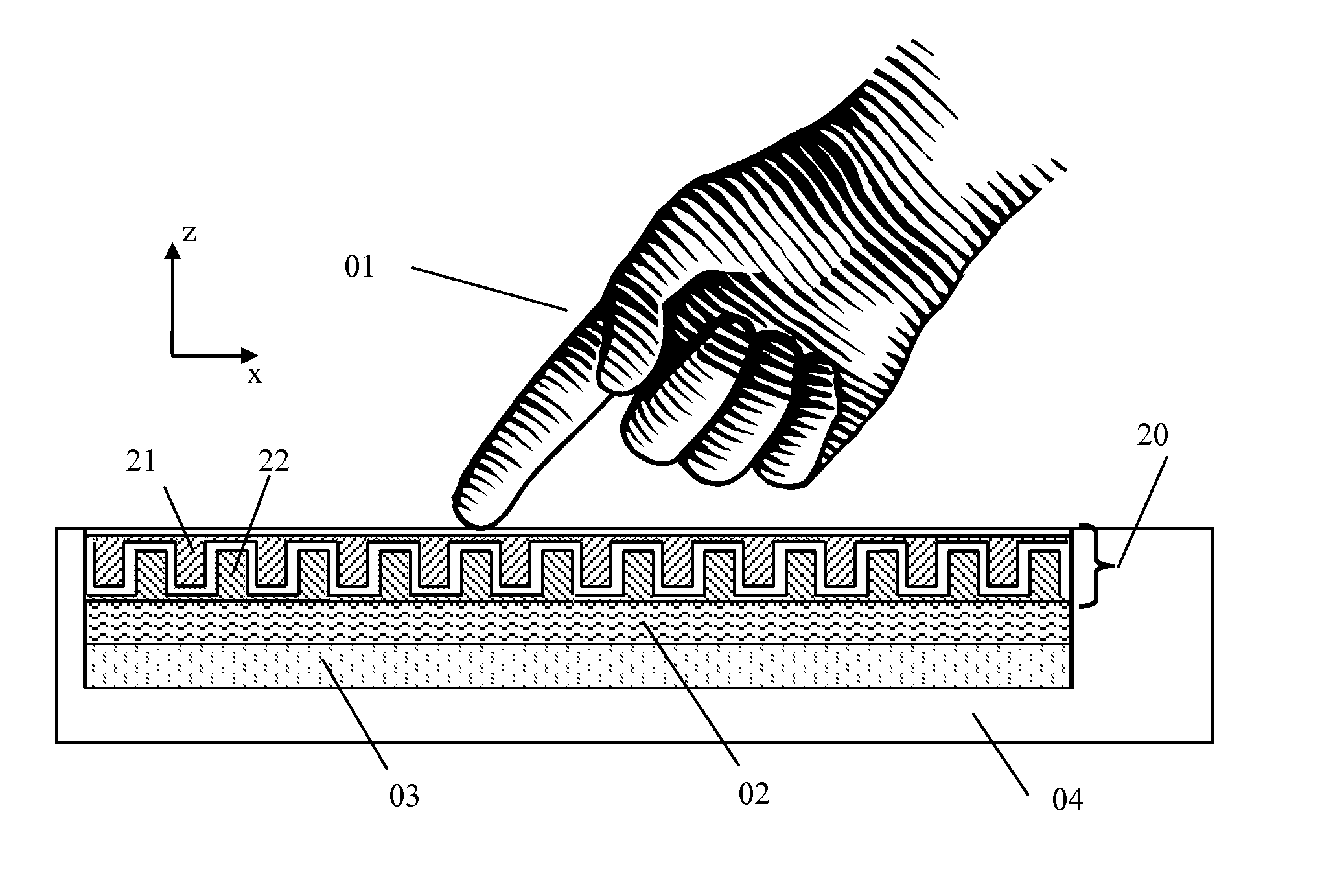
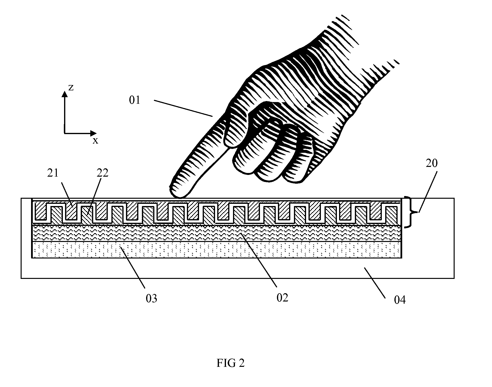
[0103]The detailed structure of the tactile feedback actuator 20 is shown in FIG. 3 and FIG. 4A. A plurality of first ridges 23a are formed on the bottom of the first substrate 21 and a plurality of complementary second ridges 23b are formed on the top of the second substrate 22. The ridges 23a,23b may be formed, for example by plasma etching a suitably masked sheet of organic polymer or glass or other transparent material serving as a substrate as described in Plasma Deposition, Treatment, and Etching of Polymers (ed. Riccardo d'Agostino) chapter 5 and is known in the science of liquid crystal display manufacturing. The reader will be aware that there are other methods by which ridges can be formed, for example, by simple milling of the surface, or by chemical etching. Alternatively the ridges can be built up on a planar surface.

[0104]The tactile feedback actuator 20 includes an electrode arrangement formed on the first and second substrates. More particularly, one or both side wa...

second embodiment

[0114]In this invention, a pulse of either positive or negative potential is applied to one electrode set (e.g. 42) of a first pair 35a to generate the time-varying potential difference across the respective electrode sets and resultant electrostatic force of attraction between the two electrode sets forming the pair. (In other words, one electrode set of the first pair 35a receives a voltage pulse whilst the other electrode set of the first pair 35a remains at a fixed potential such as the system ground.) The return motion is generated by repeating this operation on one electrode set (e.g. 43) of the other electrode pair 35b. (In other words, one electrode set of the second pair 35b receives a voltage pulse whilst the other electrode set of the second pair remains at a fixed potential such as the system ground). This is shown in FIG. 7. In State 1, V3 is at ground potential and V2 has a potential pulse applied to it (V1 and V4 are both at ground potential). This causes attraction b...

fourth embodiment

[0116]FIG. 9A shows this invention in which elastic spacers 55 are used to return the first substrate 21 to equilibrium position relative to the second substrate 22. Electrostatic forces created by the time-varying potential difference are used still to cause the initial motion, but the return force is provided by the elastic spacer 55 so as to result in the oscillatory lateral movement. The elastic spacers 55 are positioned between the moving substrate 21 and the supporting frame 56. The reader will be aware that this is not the only position at which elastic spacers 55 can be placed to cause the return force. In an alternative arrangement to this embodiment, shown in FIG. 9B, an elastic seal 57 is placed around the edge of the first substrate 21. The elastic seal57 functions like the elastic spacers 55 in serving to return the first substrate to an equilibrium position relative to the second substrate following lateral motion due to the electrostatic force created by the time-vary...


PUM


Abstract

A touch-screen device includes a display; a tactile feedback actuator arranged on the display, including a first substrate, a second substrate facing the first substrate, the first substrate and the second substrate being parallel to each other in a lateral direction, and movable relative to each other in the lateral direction; and an electrode arrangement on the first substrate and the second substrate, whereby a potential difference applied across two or more electrodes in the electrode arrangement produces an electrostatic force in the lateral direction between the first substrate and the second substrate; and a controller configured to apply a time-varying potential difference across the two or more electrodes such that the resultant electrostatic force varies in the lateral direction and induces oscillatory lateral movement of the first substrate relative to the second substrate.

Description

TECHNICAL FIELD[0001]The invention relates to a touch-screen device, and more specifically a touch-screen device including a tactile feedback actuator that can reproduce tactile sensations in response to user input. The invention further relates to a structure and control means to generate tactile sensations through oscillatory motions.BACKGROUND ART[0002]With touch-screen and touch-display devices (collectively referred to herein as “touch-screen devices”) rapidly growing in popularity, one significant shortcoming over traditional methods of data-entry has quickly become evident. The lack of tactile sensations perceived by the user when pressing “virtual” buttons on the touch-screen—the feelings of button edges and depressing the button for example—necessitates extra concentration by the user, who must look at the screen to help judge that they have correctly entered the data. Real buttons and keys help divide the mental effort amongst the senses with the sense of touch helping to ...

Claims


Application Information

Patent Timeline
IPC IPC(8): G06F3/041
CPCG06F3/041G06F3/016
Inventor KARAMATH, JAMES ROBERTBROWN, CHRISTOPHER
Owner SHARP KK
Why Eureka
Try Eureka