Alternate Viewpoint Rendering

a rendering technique and viewpoint technology, applied in the field of alternative viewpoint rendering, can solve the problems of excessive distortion of alternate viewpoint images, delays in processing speed and accuracy of alternate viewpoint images (the rendered images), and cumbersome shooting films with two cameras for stereo presentation, so as to avoid unnecessary computation and processing, and improve efficiency.

Active Publication Date: 2012-10-25
CO 3 METHOD INC
View PDF2 Cites 14 Cited by
  • Summary
  • Abstract
  • Description
  • Claims
  • Application Information

AI Technical Summary

Benefits of technology

[0006]One approach to generate alternate viewpoints is to use a two phase process that first renders the original images (based on depth information such as depth mattes) and fills smaller gaps, and a second phase that fills the remaining larger gaps. The order of pixels processed can be customized to enhance efficiency. For example, it can be beneficial to process pixels from the original image from left-to-right in some instances (e.g., to render an image with a viewpoint that is left of the original viewpoint in the source image), or to process pixels from the original image from right-to-left in other instances (e.g., to render an image with a viewpoint that is right of the original viewpoint in the source image). Further, the top-most pixels can be kept track of to avoid performing unnecessary computation and processing.

Problems solved by technology

In the field of motion pictures, it is often cumbersome to shoot a film with two cameras for stereo presentation.
However, rendering techniques often suffer from both delays in processing speed and in the accuracy of which the alternate viewpoint images (the rendered images) are generated.
Further, while the images can be filtered to speed up the process, the alternate viewpoint images may suffer from excessive distortion.
This distortion can compromise the viewing pleasure of the rendered sequences, which results in a poor viewer experience.

Method used


Image

  • Alternate Viewpoint Rendering
  • Alternate Viewpoint Rendering
  • Alternate Viewpoint Rendering

Examples


Embodiment Construction

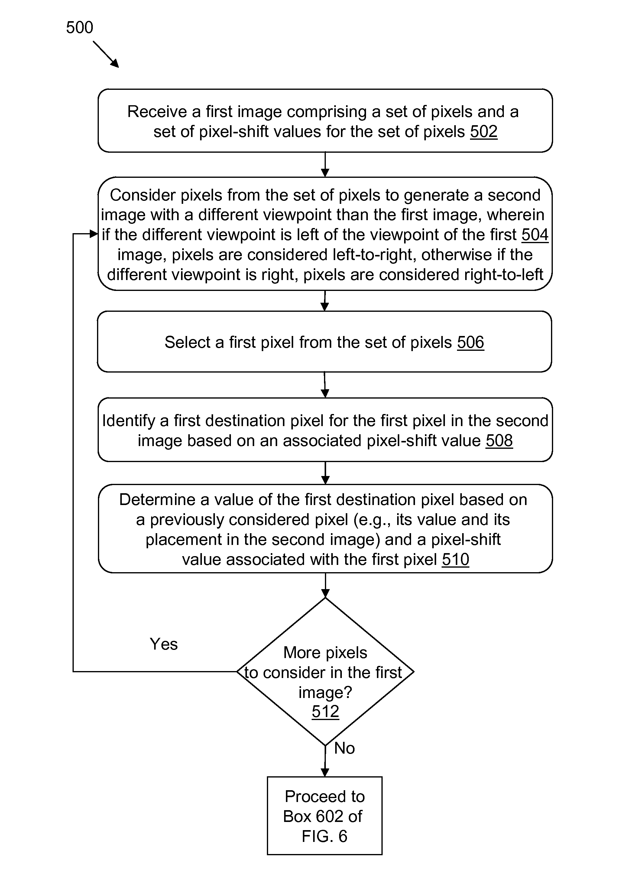
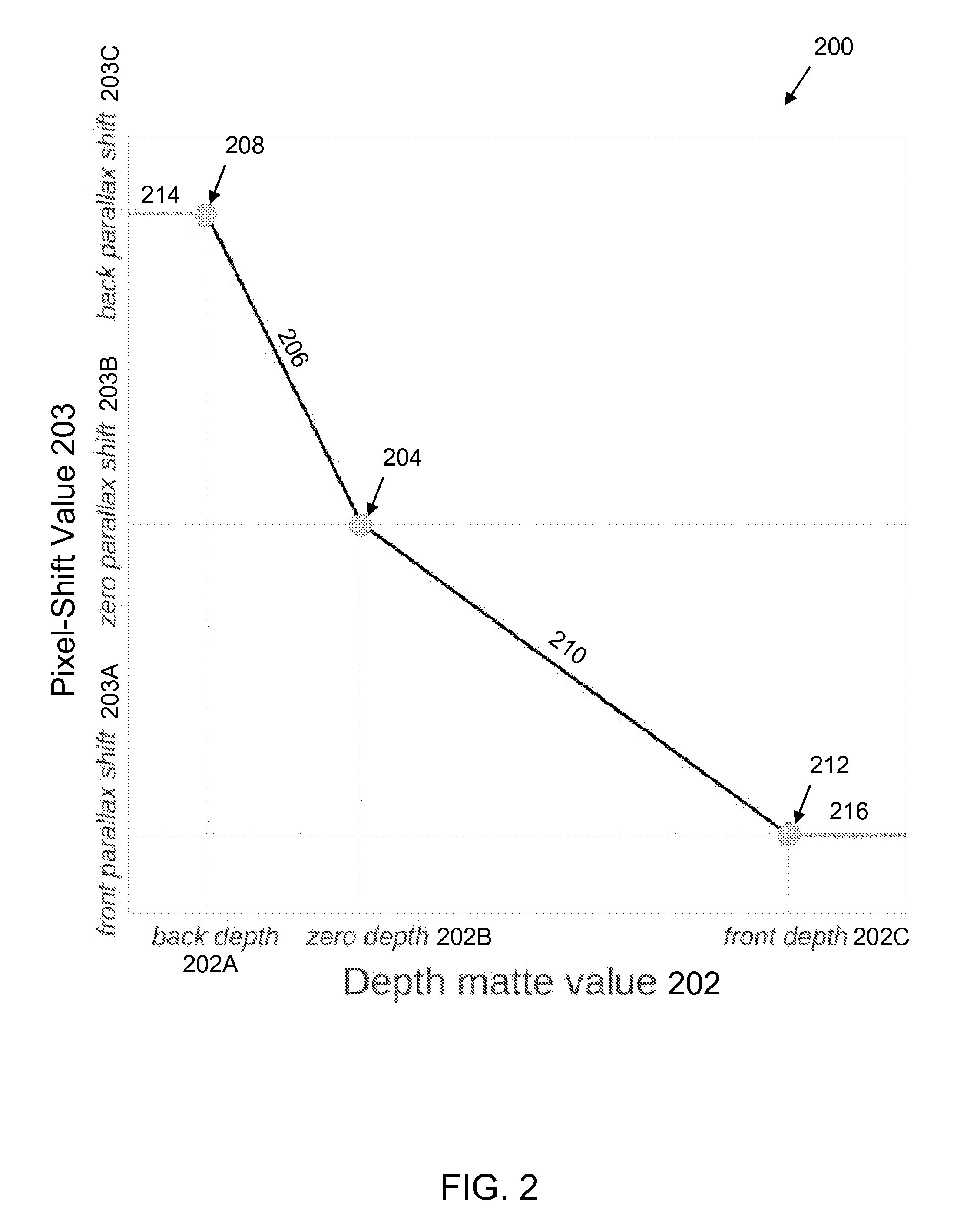
[0029]In general, computerized systems and methods are provided for generating images with alternate viewpoints from an original image. Depth information (e.g., a depth matte) is generated for the original image. Pixel-shift values that indicate how to transform the depth information into an image (e.g., an image displayed in the real world) are generated based on the depth information. The pixel-shift values and the original image are used to generate the alternate viewpoint images.

[0030]Although the specification and / or figures describe(s) the techniques in terms of particular ordered steps, these techniques work equally as well using different orders for the steps (and / or different steps) and are therefore not intended to limit the computerized systems and methods described herein.

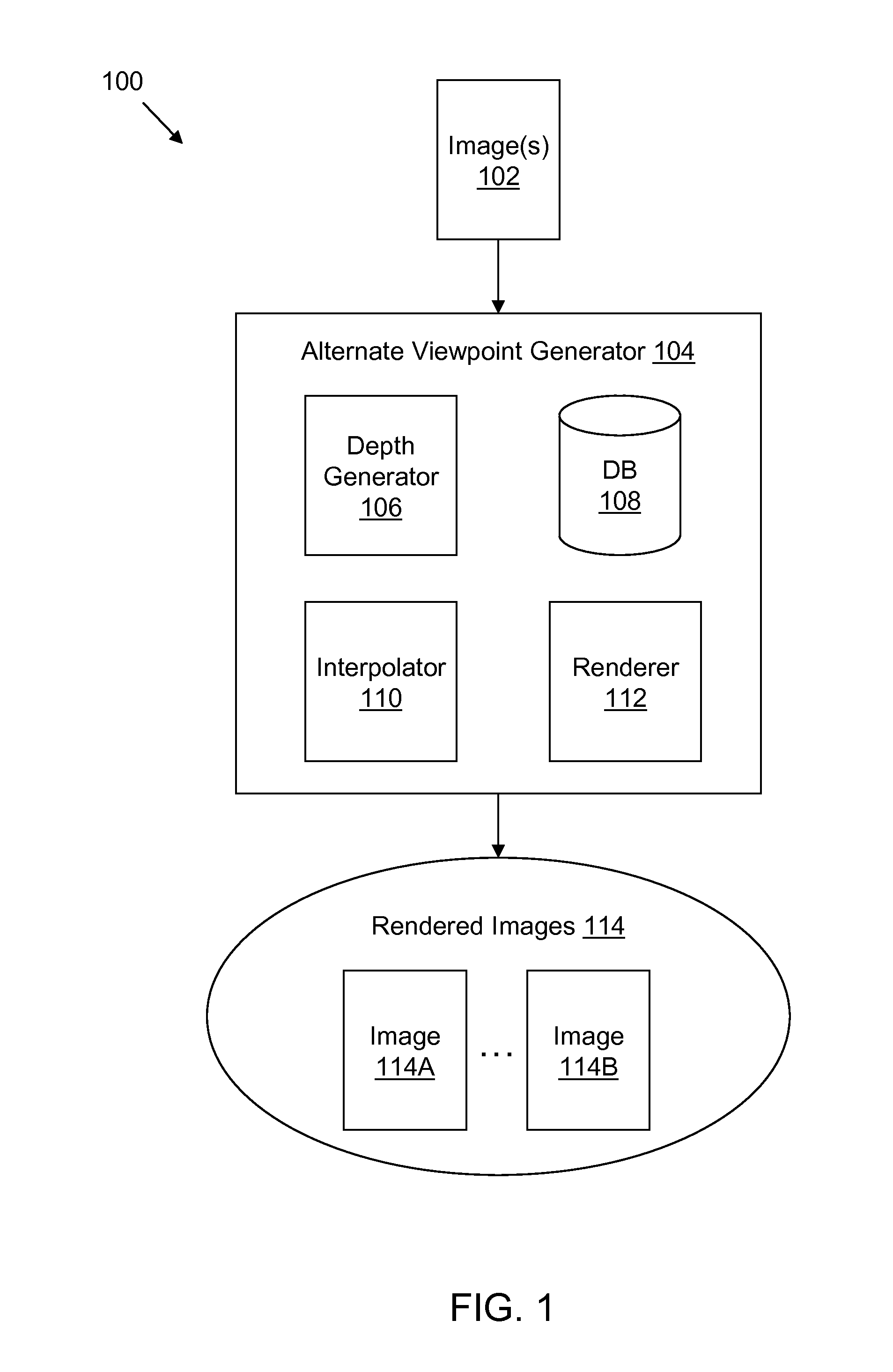
[0031]FIG. 1 is a diagram that illustrates a computerized system 100 in which an alternate viewpoint generator 104 (also referred to herein as “generator 104”) converts an original (or source) image int...


PUM


Abstract

Described are computer-based methods and apparatuses, including computer program products, for alternate viewpoint rendering. A first image and a set of pixel-shift values for the pixels in the first image are received. A portion of a second image is generated, the second image comprising a different viewpoint than a viewpoint of the first image. A first pixel from the set of pixels is selected based on the different viewpoint. A first destination pixel is identified for the first pixel in the second image based on a pixel-shift value from the set of pixel-shift values associated with the first pixel. A value of the first destination pixel is determined based on at least one of (a) a previously considered pixel from the set of pixels of the first image that is horizontally adjacent to the first pixel or (b) the pixel-shift value associated with the first pixel.

Description

FIELD OF THE INVENTION[0001]The present invention relates generally to computer-based methods and apparatuses, including computer program products, for alternate viewpoint rendering.BACKGROUND[0002]Rendering is often used to refer to a process of taking a model (for example, a three-dimensional (3D) model or an image-based model) and producing from an abstract set of data (e.g., lighting information, texture information, 3D object information, prospective and parallax information) a visual image that is a representation of that data. Rendering is often used to render alternate (or different) viewpoints of an original image. For example, an original image can be rendered into two images that simulate the left and right images that would be perceived by a person's eyes (a stereo pair). Advantageously this process can be used to create synthetic stereopsis (or artificially triggered stereo depth perception).[0003]For a geometric system, an image (or movie) can be rendered using models ...

Claims


Application Information

Patent Timeline
Patent Type & Authority Applications(United States)
IPC IPC(8): G06T3/20
CPCG06T3/20H04N13/026H04N13/261
Inventor IZUMI, KUNIAKI
Owner CO 3 METHOD INC
Why Eureka
Try Eureka