MIMO detector

a detector and mirror technology, applied in the field of mirror detectors, can solve problems such as increasing power consumption, and achieve the effect of reducing power consumption

Active Publication Date: 2012-10-25
RAYTRON
View PDF3 Cites 5 Cited by
  • Summary
  • Abstract
  • Description
  • Claims
  • Application Information

AI Technical Summary

Benefits of technology

[0006]However, the matrix of the propagation path is defined by the number of antennas of both the transmitter and the receiver (the number of data streams). Thus, as the number of antennas increases, the amount of calculation of the inverse matrix increases significantly. The amount of calculation of the inverse matrix is proportional to N3, where N represents the number of antennas. For example, the amount of calculation in a 4×4 MIMO configuration is eight times as large as the amount of calculation in a 2×2 MIMO configuration. In this case, performing the MIMO detection processing on every packet increases power consumption.
[0007]It is an object of the present invention to provide a MIMO detector capable of reducing power consumption.
[0009]According to this configuration, the processing time required to calculate the inverse matrix can be made variable according to the variation in the propagation path over time. That is, the processing time for calculating the inverse matrix can be varied according to the variation in the propagation path over time. Accordingly, for example, in the case where the variation in the propagation path over time is small, calculation of the inverse matrix can be controlled to be performed on every two or more packets. This can reduce power consumption.
[0010]Preferably, the inverse matrix calculation unit is an inverse matrix calculation circuit configured to calculate the inverse matrix, and the variable control unit variably controls the processing time required to calculate the inverse matrix, by variably controlling a clock frequency and a voltage that are to be supplied to the inverse matrix calculation circuit. This can reduce power consumption with a simple configuration.
[0014]According to the present invention, the processing time required to calculate an inverse matrix can be made variable according to the variation in the propagation path over time. That is, the processing time for calculating an inverse matrix can be varied according to the variation in the propagation path over time. Accordingly, for example, in the case where the variation in the propagation path over time is small, calculation of an inverse matrix can be controlled to be performed on every two or more packets. This can reduce power consumption.

Problems solved by technology

In this case, performing the MIMO detection processing on every packet increases power consumption.

Method used


Image

  • MIMO detector
  • MIMO detector
  • MIMO detector

Examples


Embodiment Construction

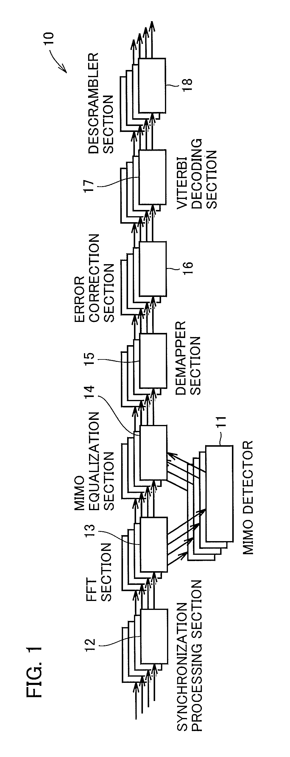
[0029]An MIMO detector according to an embodiment of the present invention will be described below with reference to the accompanying drawings. FIG. 1 is a block diagram showing the configuration of a receiver 10 that is used in MIMO-OFDM wireless communication. In the MIMO-OFDM wireless communication, a plurality of propagation paths are formed between a plurality of transmitting and receiving antennas to provide wireless communication. FIG. 1 shows an example using four receiving antennas. Referring to FIG. 1, the receiver 10 receives data from a transmitter including four transmitting antennas, not shown. The receiver 10 includes a synchronization processing section 12 configured to synchronize data between the transmitter and the receiver 10, a fast Fourier transform (FFT) section 13 configured to convert an OFDM signal to a plurality of subcarriers to perform a channel equalization on the subcarriers, a MIMO equalization section 14 configured to perform, after MIMO detection pr...


PUM


Abstract

A MIMO detector for use in MIMO-OFDM wireless communication that forms a plurality of propagation paths by using a plurality of transmitting and receiving antennas includes: an inverse matrix calculator operating as an inverse matrix calculation unit configured to calculate an inverse matrix of a matrix of the propagation path based on a signal received by a receiver; a detection speed controller operating as an estimation unit configured to estimate a variation in the propagation path over time; and a phase synchronization circuit and a regulator configured to variably control a processing time required to calculate the inverse matrix by the inverse matrix calculator, according to the variation in the propagation path over time estimated by the detection speed controller. The MIMO detector is provided on the side of the receiver of the wireless communication.

Description

TECHNICAL FIELD[0001]The present invention relates to MIMO detectors, and more particularly to MIMO detectors included in receivers having a large number of receiving antennas.BACKGROUND ART[0002]There has been a demand for higher speed communication and larger communication data capacity in recent wireless communication technology. A MIMO-OFDM technique combining multi input multi output (MIMO) and orthogonal frequency division multiplexing (OFDM) has attracted attention in response to such a demand. MIMO is a technique using a plurality of antennas by both a transmitter and a receiver, and OFDM is a modulation technique that is used in next-generation mobile communication such as long term evolution (LTE) due to its excellent bandwidth efficiency and high tolerance to the multipath fading environment.[0003]An example of a receiver of the MIMO technique is disclosed in Japanese Unexamined Patent Application Publication No. 2004-179822 (paragraphs [0003] to [0008]).[0004]According t...

Claims


Application Information

Patent Timeline
Patent Type & Authority Applications(United States)
IPC IPC(8): H04L27/14
CPCH04B7/0439H04B7/0697H04B7/0854H04L25/0204H04L25/0222H04L25/0242H04L27/2647H04L27/2657H04L27/2675H04L25/0224
Inventor MIYANAGA, YOSHIKAZUYOSHIZAWA, SHINGO
Owner RAYTRON
Why Eureka
Try Eureka