
Precision turning tool

a technology of precision turning tools and cutting tools, which is applied in the direction of boring/drilling equipment, thread cutting machines, measuring/indication equipment, etc., can solve the problems of limited total travel of tool slides, difficult to read scales, and difficult to achieve cutting speeds in the case of such precision turning tools. , to achieve the effect of simplifying the production and assembly of precision turning tools

Active Publication Date: 2012-10-25
WOHLHAUPTER
View PDF12 Cites 18 Cited by
  • Summary
  • Abstract
  • Description
  • Claims
  • Application Information

AI Technical Summary

Benefits of technology

[0011]The precision turning tool according to the invention is characterized by a mounting of the cutting plate carrier on the end of the tool slide protruding out of the tool body in a direction of adjustment, wherein the distance of adjustment can be read directly on the display unit. The mounting on the end of the tool slide protruding out of the tool body in a direction of adjustment enables the tool slide to be adjusted over a considerable distance of adjustment, preferably a distance of adjustment of more than 5 mm, in particular a distance of adjustment of 7 to 9 mm. The distance of adjustment can be read by the user in a simple manner on the display unit. It may, in particular, be provided for the distance of adjustment to be shown directly on the display unit in micrometers.
[0044]It is favorable when the compensating slide is surrounded in circumferential direction by an elastic guiding element which abuts on the wall of a recess of the tool body which accommodates the compensating slide.

Problems solved by technology

The reading of the scale does, however, require some practice.
However, such precision turning tools enable, so far, only a lateral mounting of the cutting plate carrier on the longitudinal side of the tool slide facing away from a shaft of the tool body.
The total travel which can be achieved with the tool slide is very limited.
Also, the cutting speeds which can be achieved are not very high in the case of such precision turning tools.

Method used


Image

  • Precision turning tool
  • Precision turning tool
  • Precision turning tool

Examples


Embodiment Construction

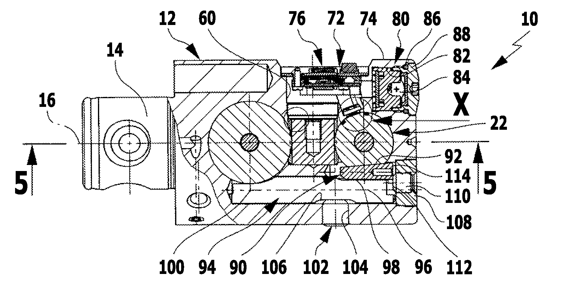
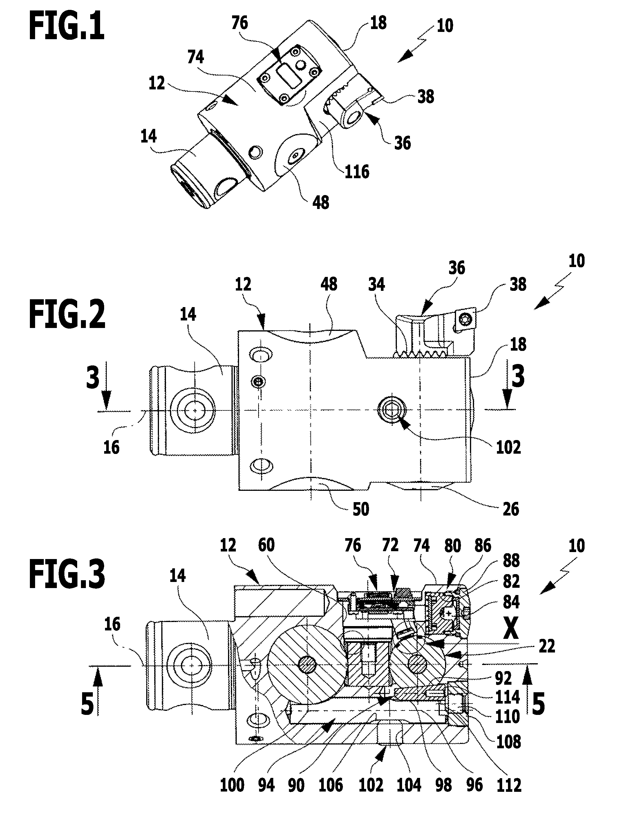
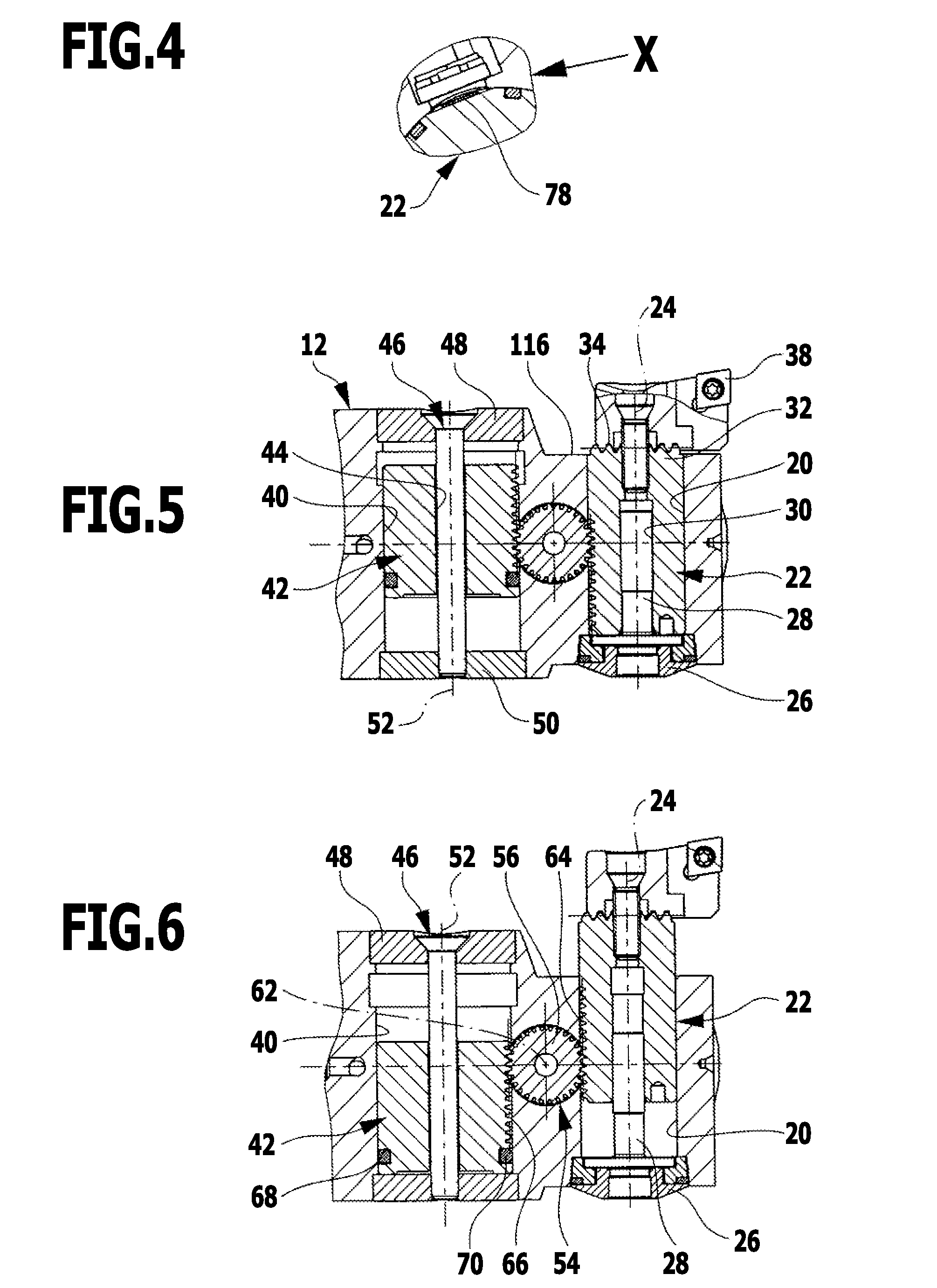
[0055]A first embodiment of a precision turning tool according to the invention, which is given altogether the reference numeral 10, is illustrated schematically in FIGS. 1 to 6. It comprises an essentially circular cylindrical tool body 12, from which a shaft 14 projects which, for example by means of a chuck, can be clamped into a rotatingly driven spindle of a machine tool and so the precision turning tool 10 rotates about a common axis of rotation 16 together with the spindle of the machine tool.

[0056]Adjacent to an outer face 18 of the tool body 12 facing away from the shaft 14 the tool body 12 has a front recess 20 which passes through the tool body 12 at right angles to the axis of rotation 16 and into which a tool slide 22 is inserted. The tool slide 22 can be adjusted along an axis of adjustment 24 which is aligned at right angles to the axis of rotation 16. For this purpose, a precision adjustment mechanism is used which has a cover 26 which is held at one end of the front...


PUM

PropertyMeasurementUnit
Forceaaaaaaaaaa
Displacementaaaaaaaaaa

Abstract

A precision turning tool has a rotatingly drivable tool body. A tool slide and corresponding compensating slide are displaceably mounted in the tool body. The tool slide is displaceable along an axis of adjustment aligned at right angles to an axis of rotation of the tool body. The compensating slide is automatically displaceable along an axis of compensation aligned parallel to the axis of adjustment contrary to the movement of the tool slide to compensate for any imbalance. At an end projecting out of the tool body in the direction of adjustment the tool slide has a mounting surface, on which a cutting plate carrier can be mounted. An electronic distance measuring system is provided with a display unit and an energy supply device, wherein the distance of adjustment of the tool slide can be detected by means of the distance measuring system and displayed.

Description

[0001]This application is a continuation of international application number PCT / EP2010 / 066284 filed on Oct. 27, 2010 and claims the benefit of German application number 10 2009 051 843.6 filed on Oct. 29, 2009.[0002]The present disclosure relates to the subject matter disclosed in international application number PCT / EP2010 / 066284 of Oct. 27, 2010 and German application number 10 2009 051 843.6 of Oct. 29, 2009, which are incorporated herein by reference in their entirety and for all purposes.BACKGROUND OF THE INVENTION[0003]The invention relates to a precision turning tool with a tool body rotatingly drivable about an axis of rotation, a tool slide and a compensating slide coupled to the tool slide via a transmission mechanism being displaceably mounted in said tool body, wherein the tool slide is displaceable by means of a precision adjustment mechanism along an axis of adjustment aligned at right angles to the axis of rotation, and wherein the compensating slide is automatically...

Claims


Application Information

Patent Timeline
IPC IPC(8): B23B29/034B23Q17/22
CPCB23B29/03407B23Q17/2225Y10T408/21Y10T408/8598B23B2260/128Y10T408/85995B23B2250/04
Inventor BUCK, GUENTER
Owner WOHLHAUPTER
Learn More