Magnetic heat pump apparatus
- Summary
- Abstract
- Description
- Claims
- Application Information
AI Technical Summary
Benefits of technology
Problems solved by technology
Method used
Image
Examples
first embodiment
Modifications of First Embodiment
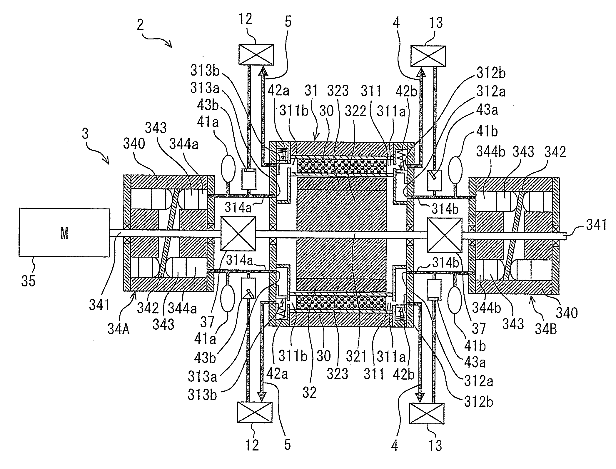
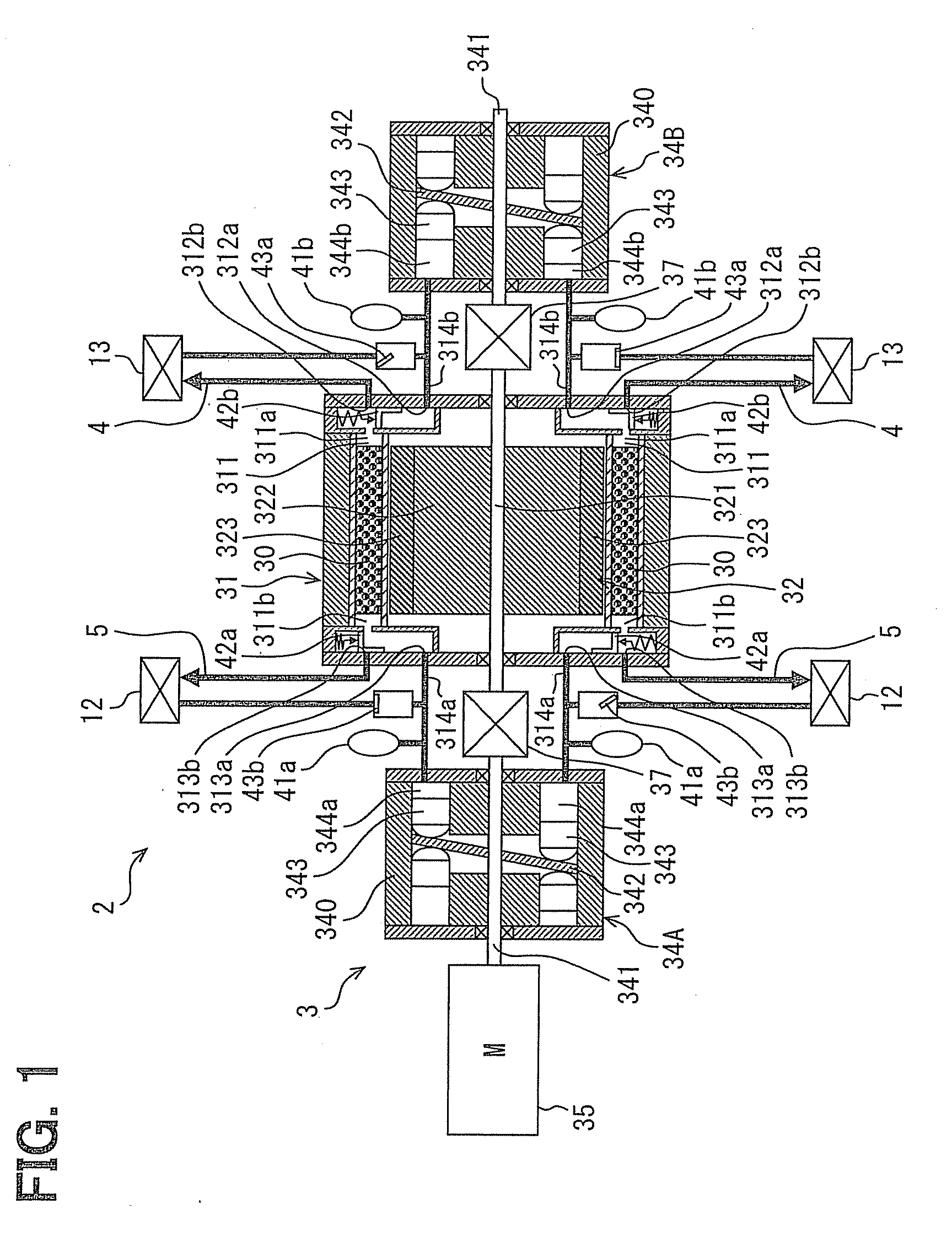
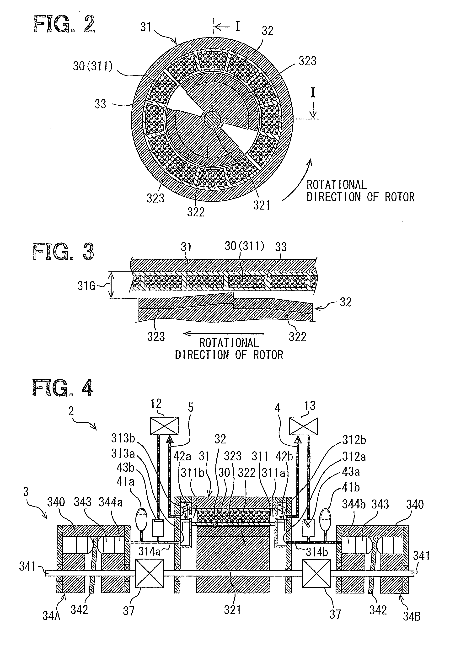
[0177]For example, the magnetic-field control unit may be modified in a way of a magnetic-field control unit 32A shown in FIG. 11. The magnetic-field control unit 32A has a magnetic resisting member 324, which is attached at the outer peripheral surface of each permanent magnet 3239 and extending in the rotational direction of the rotor 322. The permanent magnet 3239 extends in the rotational direction and has a cross section of an arc shape on a plane perpendicular to the rotational shaft 321. The permanent magnet 3239 has a constant thickness in the radial direction.
[0178]As shown in detail in FIG. 12, in which a relevant portion is expanded in a straight direction, the magnetic resisting member 324 is composed of multiple different materials arranged in the rotational direction of the rotor 322, each of which has a magnetic resistance value different from one another (for example, resin having a large magnetic resistance value and iron having a lo...
second embodiment
[0196]A second embodiment of the present disclosure will be explained with reference to FIGS. 18 and 19.
[0197]A fluid-speed pattern of the heat medium as well as an applying pattern of the magnetic field of the second embodiment is different from those of the first embodiment. The same reference numerals to the first embodiment are used in the second embodiment.
[0198]FIG. 18 is a graph showing a change of fluid speed of the heat medium in the working chamber 311 of the present embodiment. FIG. 19 is a graph showing a change of the magnetic field to be applied to the magnetic working material 30 in the working chamber 311.
[0199]A magnetic refrigerating system of the present embodiment is almost the same to that of the first embodiment. The fluid-speed pattern of FIG. 18 is obtained in the present embodiment, in which a shape of the swash plate 342 is changed a bit.
[0200]In the first embodiment, six different magnetic-field control units 32 (including the modifications 32A to 32E) are...
third embodiment
[0222]A third embodiment of the present disclosure will be explained with reference to FIG. 20.
[0223]The third embodiment differs from the first embodiment in that the heat-exchange container device 31 is divided into two container units, one of which is a high-temperature side container unit 31a for generating heat energy by the magnetocaloric effect and the other of which is a low-temperature side container unit 31b for generating cold energy by the magnetocaloric effect. In the same manner to the second embodiment, the same reference numerals for designating the same and / or similar parts and components are used in the present embodiment.
[0224]As shown in FIG. 20, the high-temperature side and the low-temperature side container units 31a and 31b are coaxially arranged with one refrigerant pump 34, wherein the refrigerant pump 34 is arranged between the container units 31a and 31b.
[0225]Each of the container units 31a and 31b is formed in a cylindrical hollow shape. Multiple worki...
PUM
 Abstract
Description
Claims
Application Information
 - R&D
- Intellectual Property
- Life Sciences
- Materials
- Tech Scout
- Unparalleled Data Quality
- Higher Quality Content
- 60% Fewer Hallucinations
Browse by: Latest US Patents, China's latest patents, Technical Efficacy Thesaurus, Application Domain, Technology Topic, Popular Technical Reports.
© 2025 PatSnap. All rights reserved.Legal|Privacy policy|Modern Slavery Act Transparency Statement|Sitemap|About US| Contact US: help@patsnap.com


