Illumination device
- Summary
- Abstract
- Description
- Claims
- Application Information
AI Technical Summary
Benefits of technology
Problems solved by technology
Method used
Image
Examples
first embodiment
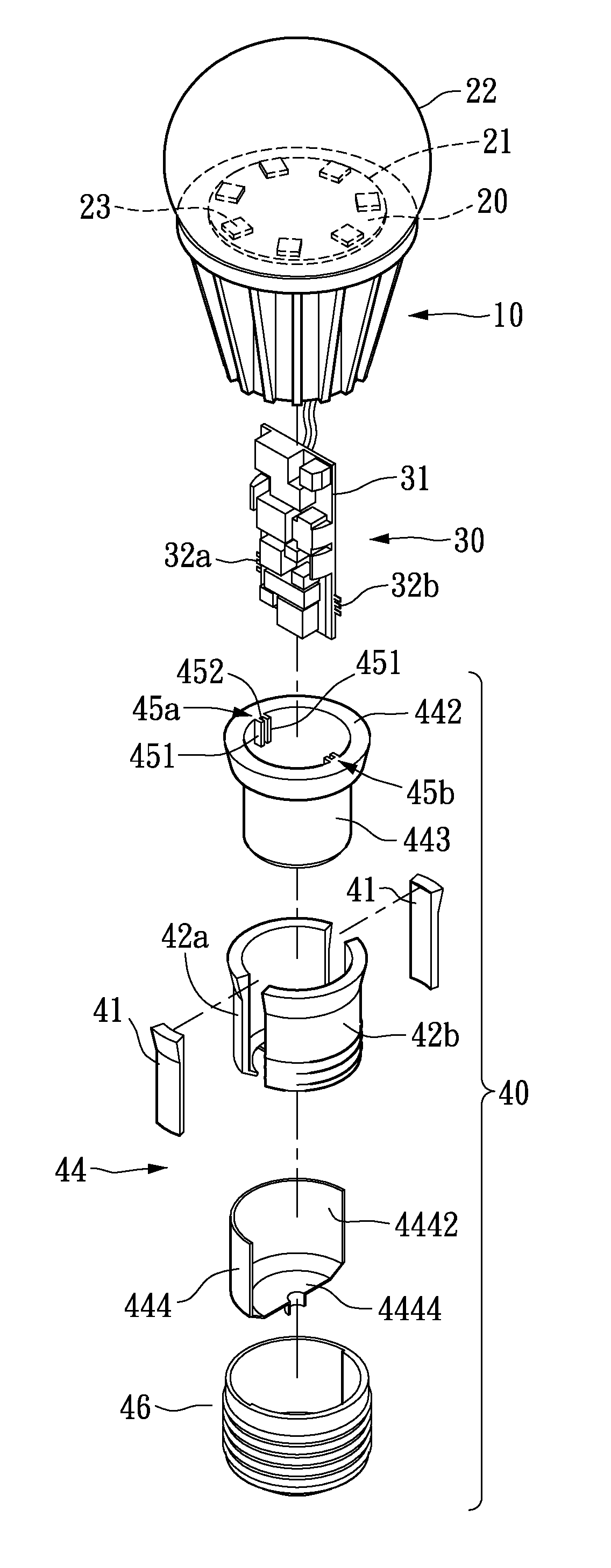
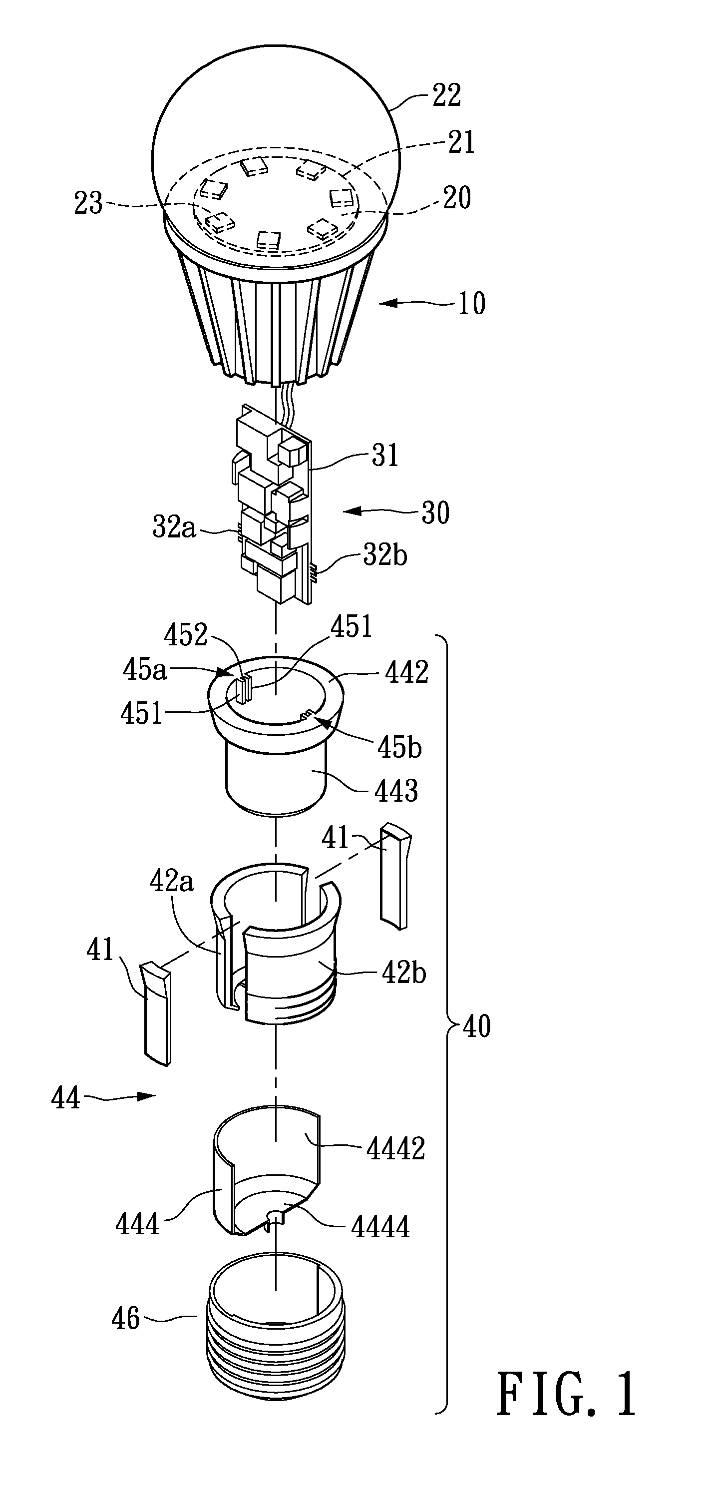
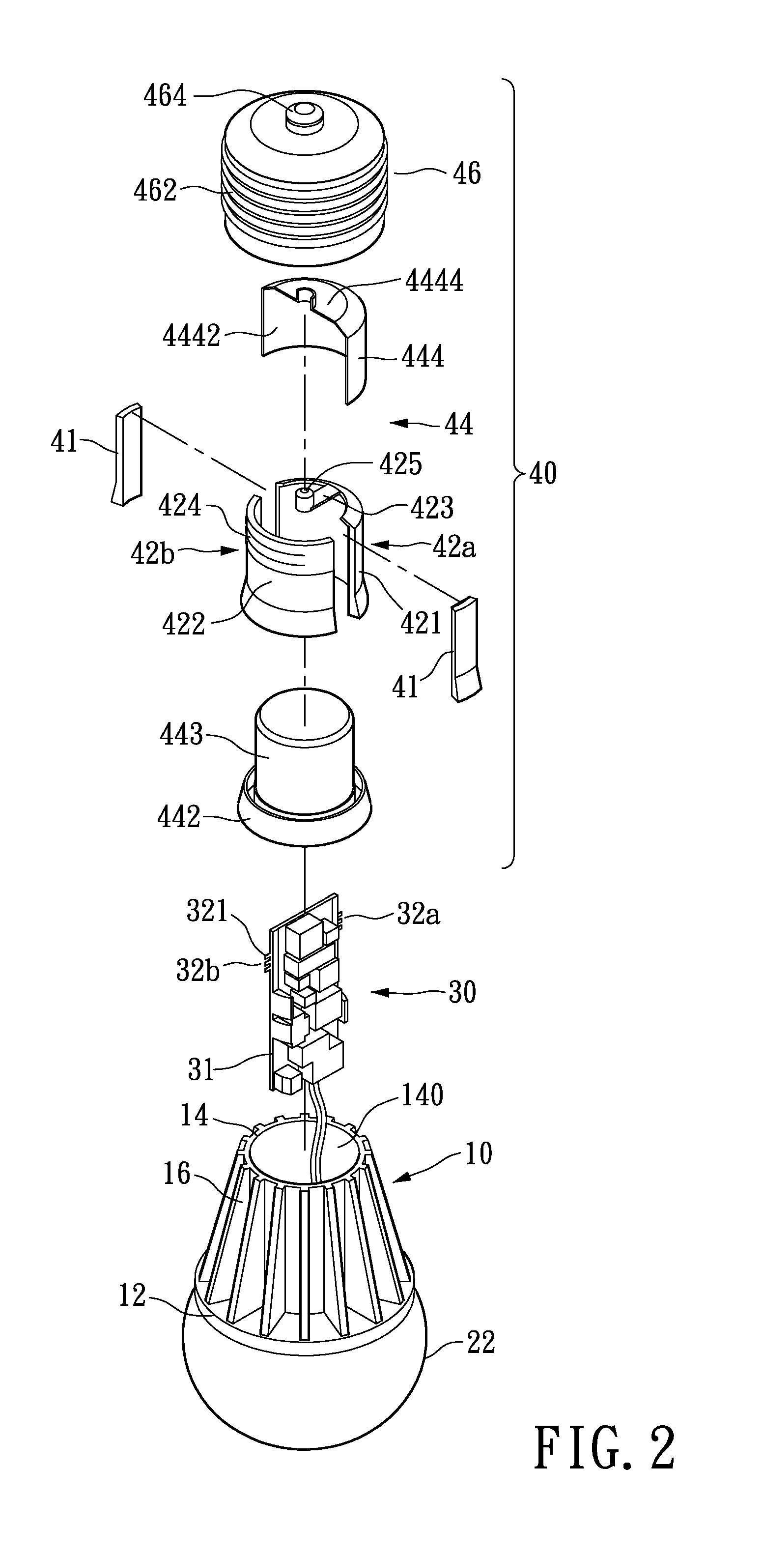
[0036]Please refer to FIG. 5, which shows a locally enlarged cross-sectional diagram around the lamp base of a first embodiment according to the present invention. The first electrode 42a and the second electrode 42b are respectively inwardly exposed through the contact ports 45a, 45b. When the electrical contact members 32a, 32b are inserted into the contact ports 45a, 45b, the pins 321 (as shown in FIG. 2) of the electrical contact members 32a, 32b may establish contact with the first electrode 42a and the second electrode 42b, so as to achieve electrical connection. Thus, the driver 30 may be detachably plugged into the lamp base 40; this arrangement provides the benefits of quick assembly, solder free, and easy replacement of the electrical components. Comparing with conventional designs, the bulb in accordance with the present invention does not require conducting wires to connect the driver 30 to the lamp base 40.
second embodiment
[0037]Please refer to FIG. 5A, which shows a locally enlarged cross sectional diagram of the lamp base 40 according to the present invention. Comparing with the previous embodiment illustrated in FIG. 5, the each of the first and the second electrodes 42a and 42b of the instant embodiment may respectively include at least one branch terminal portion (hereinafter referred to as the contact branch) 426a / 426b extending through the contact ports 45a, 45b. In the instant embodiment, each of the first and the second electrodes 42a and 42b has three contact branches (426a / 426b). Namely, the contact branches 426a, 426b extending through the contact port 45a, 45b may be branched through the inner wall of the position member 451. Thus, the contact branches 426a / 426b may establish electrical connection with the pin of the electrical contact members 32a, 32b of the driver 30.
[0038]The specific number and arrangement of the electrical contact member (32 / 32a / 32b) and the contact port (45 / 45a / 45b)...
third embodiment
[0039]Please refer to FIG. 5B, which shows an overhead cross sectional diagram of the lamp base according to present invention. This embodiment adapts a single integrated electrical contact member 32 having two pins 321 of different polarities protrudingly arranged on the same side of the driver 30. Correspondingly, the contact port 45 includes a slot 452 and a pair of inwardly extended positioning members 451. The first electrode 42a and the second electrode 42b are separately exposed from the contact port 45. Herein, by extending the first and second electrodes along the axial direction of the bulb, the extending portions of the first and second electrodes 42a, 42b may act as the positioning member 451 for positioning the driver 30. The material of the positioning member is not limited to metal; the positioning member 451 may also be made of an insulator extending from the inner wall of insulating unit 44.
PUM
 Abstract
Description
Claims
Application Information
 - R&D
- Intellectual Property
- Life Sciences
- Materials
- Tech Scout
- Unparalleled Data Quality
- Higher Quality Content
- 60% Fewer Hallucinations
Browse by: Latest US Patents, China's latest patents, Technical Efficacy Thesaurus, Application Domain, Technology Topic, Popular Technical Reports.
© 2025 PatSnap. All rights reserved.Legal|Privacy policy|Modern Slavery Act Transparency Statement|Sitemap|About US| Contact US: help@patsnap.com


