
Suppression of coherence effects in fiber lasers

a fiber laser and coherence effect technology, applied in the field of lasers, can solve problems such as depolarization of laser signals, and achieve the effects of reducing laser noise, reducing laser noise, and increasing power and energy outpu

Inactive Publication Date: 2012-11-01
BERENDT MARTIN OLE +1
View PDF5 Cites 26 Cited by
  • Summary
  • Abstract
  • Description
  • Claims
  • Application Information

AI Technical Summary

Benefits of technology

[0018]An advantage of the present invention is that it allows higher amplification gain without component damage, allowing for lasers with greater power and energy output. As higher gain can be extracted per amplifier, the invention allows for lower cost systems since less amplification stages are needed for a given output power. Suppression of coherence effects lead to improved stability of the laser output power. The use of the invention will also result in a reduced degree of polarization of the laser output, which will by itself add value in processes where the otherwise random output polarization gives a varying processing result.

Problems solved by technology

The decorrelator may be longer than a coherence length of the oscillator resulting in depolarization of the laser signal.

Method used


Image

  • Suppression of coherence effects in fiber lasers
  • Suppression of coherence effects in fiber lasers
  • Suppression of coherence effects in fiber lasers

Examples


Embodiment Construction

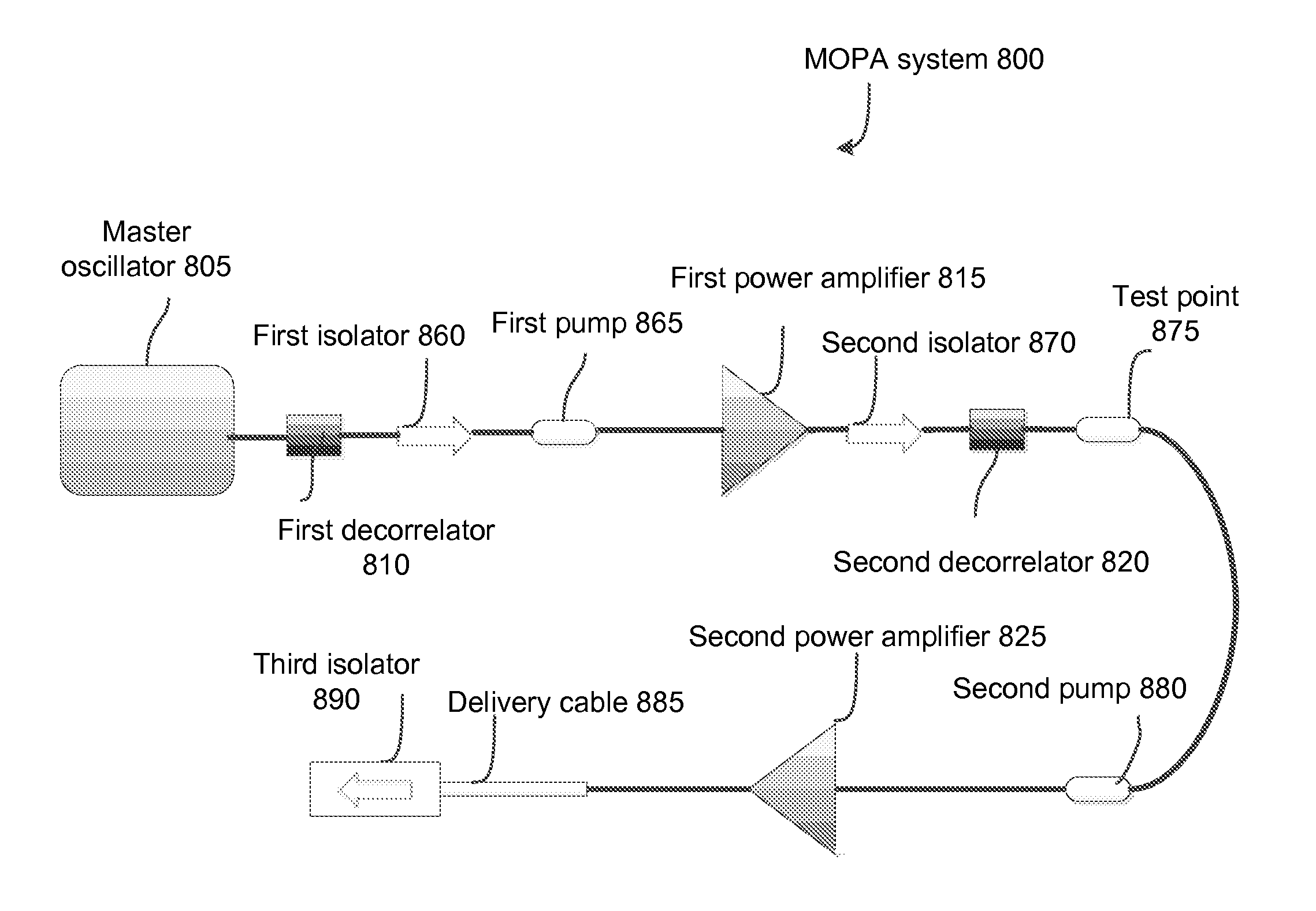
[0030]Further features and advantages of the invention, as well as the structure and operation of various embodiments of the invention, are described in detail below with reference to the accompanying FIGS. 1-11, wherein like reference numerals refer to like elements. Although the invention is described in the context of high power fiber laser oscillators, one of ordinary skill in the art can apply these concepts to other laser designs, such as gas lasers, excimer lasers, solid-state lasers, fiber lasers, photonic crystal lasers, semiconductor lasers, glass lasers, and Raman lasers. For the purposes of this present disclosure, coherence effects and random backscattering are used interchangeably, and they may include, but are not limited to: Raman scattering, Stimulated Brillouin Scattering (SBS) or Brillouin Scattering, Rayleigh scattering, spurious / random lasing, backscattering, resonant random backscatter, backscatter effects, resonant backscatter lasing, seeded random lasing, see...


PUM


Abstract

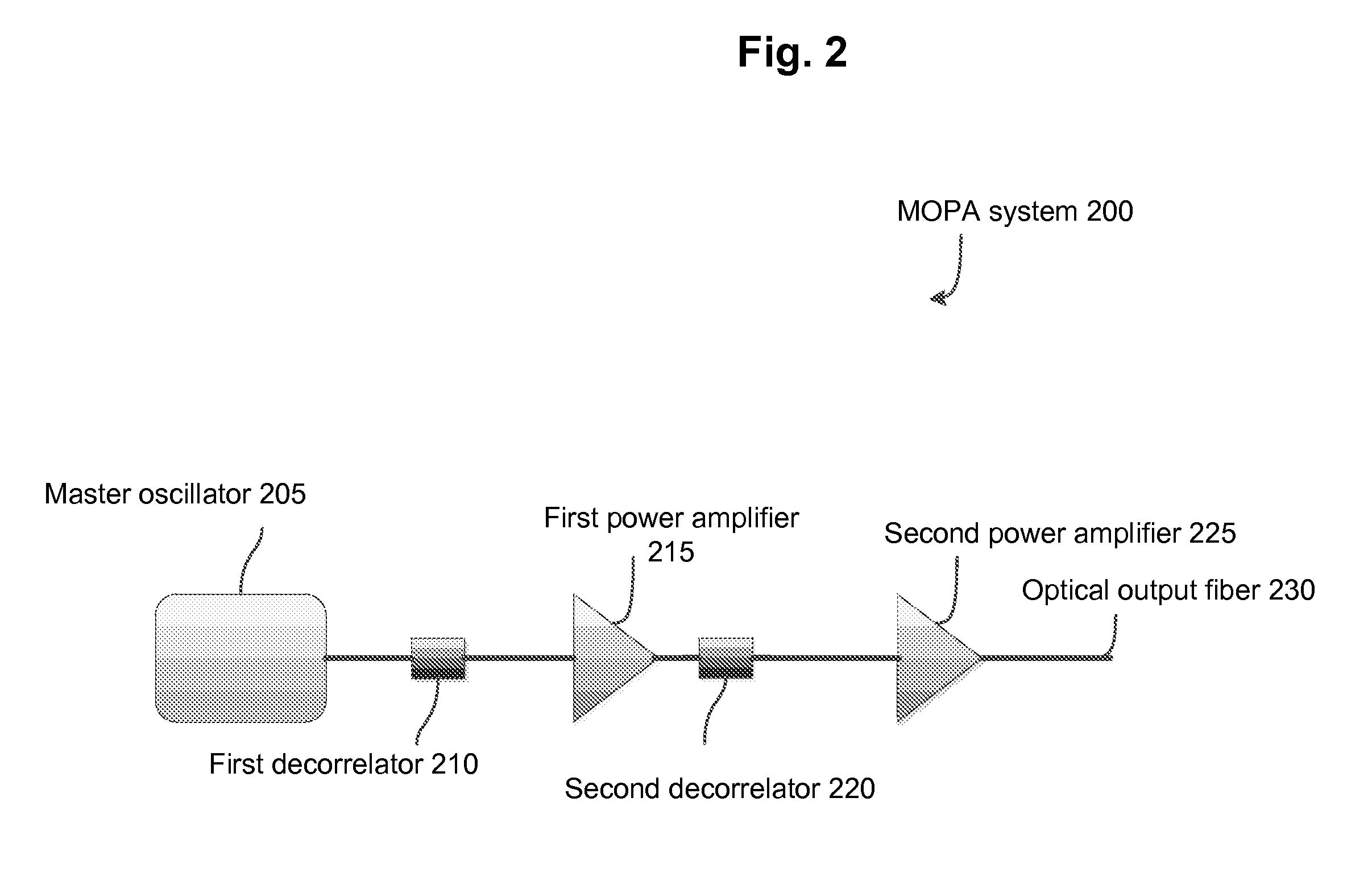
The present invention provides, in at least one embodiment, a scheme which is effective in suppressing detrimental coherence effects such as random backscatter. In a fiber laser having a master oscillator power amplifier design, inserting a decorrelator in between the master oscillator and a first power amplifier or inserting a decorrelator in between the first power amplifier and a second power amplifier to reduce random backscatter, which allows for much more energy to be stored and higher gain without the risk of catastrophic optical damage, thus increasing the peak power that can be delivered as useful laser power. Backscattering can be further reduced by having the master oscillator depolarized, injection locked, and spectrally broadened to reduce the coherence length of the master oscillator.

Description

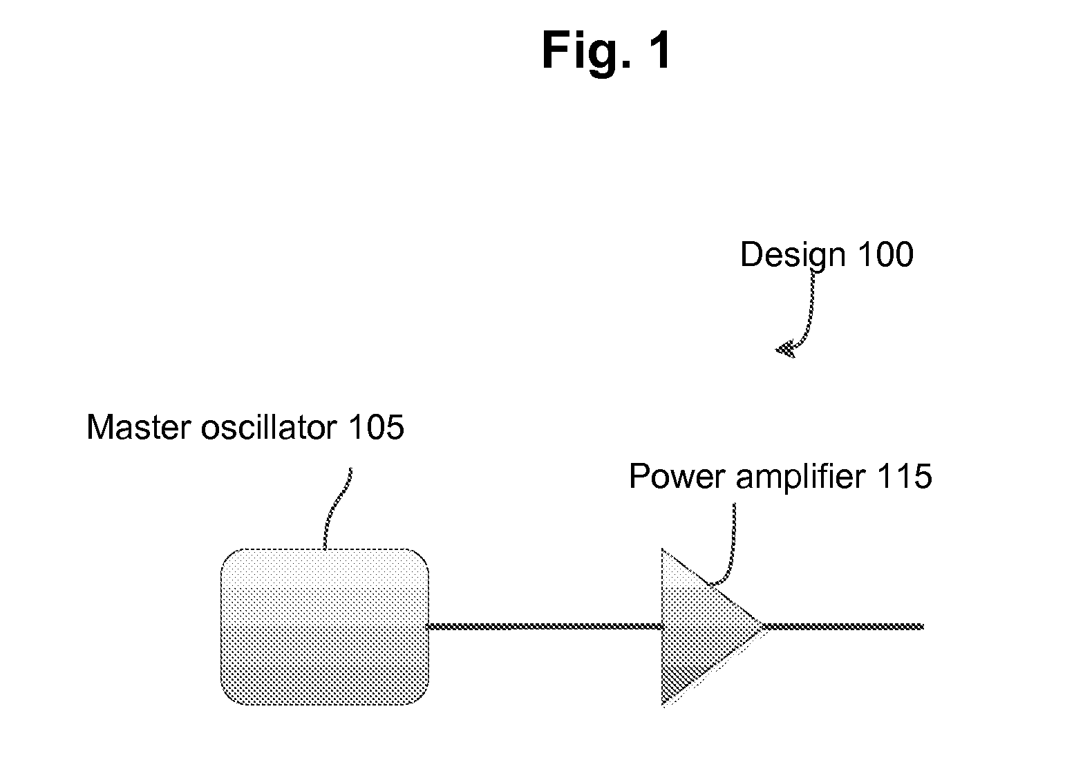
BACKGROUND OF THE INVENTION[0001]1. Field of Invention[0002]The invention relates generally to lasers, and more particularly, to techniques for suppressing detrimental coherence effects in high power fiber lasers.[0003]2. Description of Related Art[0004]Power scaling of a laser increases the laser's output power without changing the laser's principle of operation or output characteristics. Power scaling typically requires a powerful pump source and strong amplification associated with high laser medium gain levels. A popular way of achieving power scaling is through implementation of a master oscillator power amplifier (MOPA) design.[0005]FIG. 1 illustrates a conventional master oscillator power amplifier design 100 having a master oscillator 105 and a power amplifier 115. The master oscillator 105 produces a laser signal, and the power amplifier 115 is used to increase the power of the signal while preserving its main properties. The master oscillator 105 does not have to be very p...

Claims


Application Information

Patent Timeline
Patent Type & Authority Applications(United States)
IPC IPC(8): H01S3/098H01S3/10
CPCH01S3/06754H01S3/10023H01S3/10061H01S3/06758H01S3/005H01S3/0064H01S2301/03H01S3/10092
Inventor BERENDT, MARTIN OLEALVES PEREIRA, DIONISIO CERQUEIRA
Owner BERENDT MARTIN OLE
Learn More