Exhaust device having deflection plates

a technology of exhaust device and deflection plate, which is applied in ventilation systems, heating types, stoves or ranges, etc., can solve the problems of affecting the efficiency of operation, so as to prevent the leakage of pollutants or soot, and effectively exhaust high-temperature pollutants or soot

Inactive Publication Date: 2012-11-01
HUANG RONG FUNG
View PDF24 Cites 10 Cited by
  • Summary
  • Abstract
  • Description
  • Claims
  • Application Information

AI Technical Summary

Benefits of technology

[0006]An object of the present invention is to provide an exhaust device having deflection plates, where an elongate air-extraction slot is provided on the bottom of the air-extraction hood, and a

Problems solved by technology

However, when the door of the conventional exhaust cabinet is open, based on the principles of Aerodynamics, harmful gas within the cabinet may escape easily around the peripheries of the door.
Moreover, the leakage may be even severer when operators are opening or closing the door, or stand in front of the open cabinet for experimental operations, or when there are ambient drafts or there are people walking by.
The main reason of the leakage is that vortex and turbulence are easily formed around the peripheries of the cabinet door and around operators' chests.
The vortex and turbulence may result in the mass and momentum exchange between the inside and the outside of the cabinet.
Therefore, the leakage of the pollutants in the cabinet is scarcely avoidable.
Unfortunately, there is nearly no conventional exhaust cabinet can be used without opening and closing its door.
Besi

Method used


Image

  • Exhaust device having deflection plates
  • Exhaust device having deflection plates
  • Exhaust device having deflection plates

Examples


first embodiment

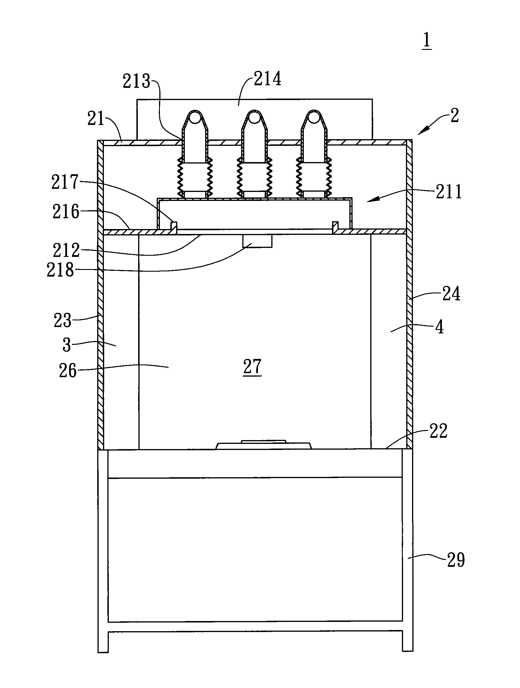
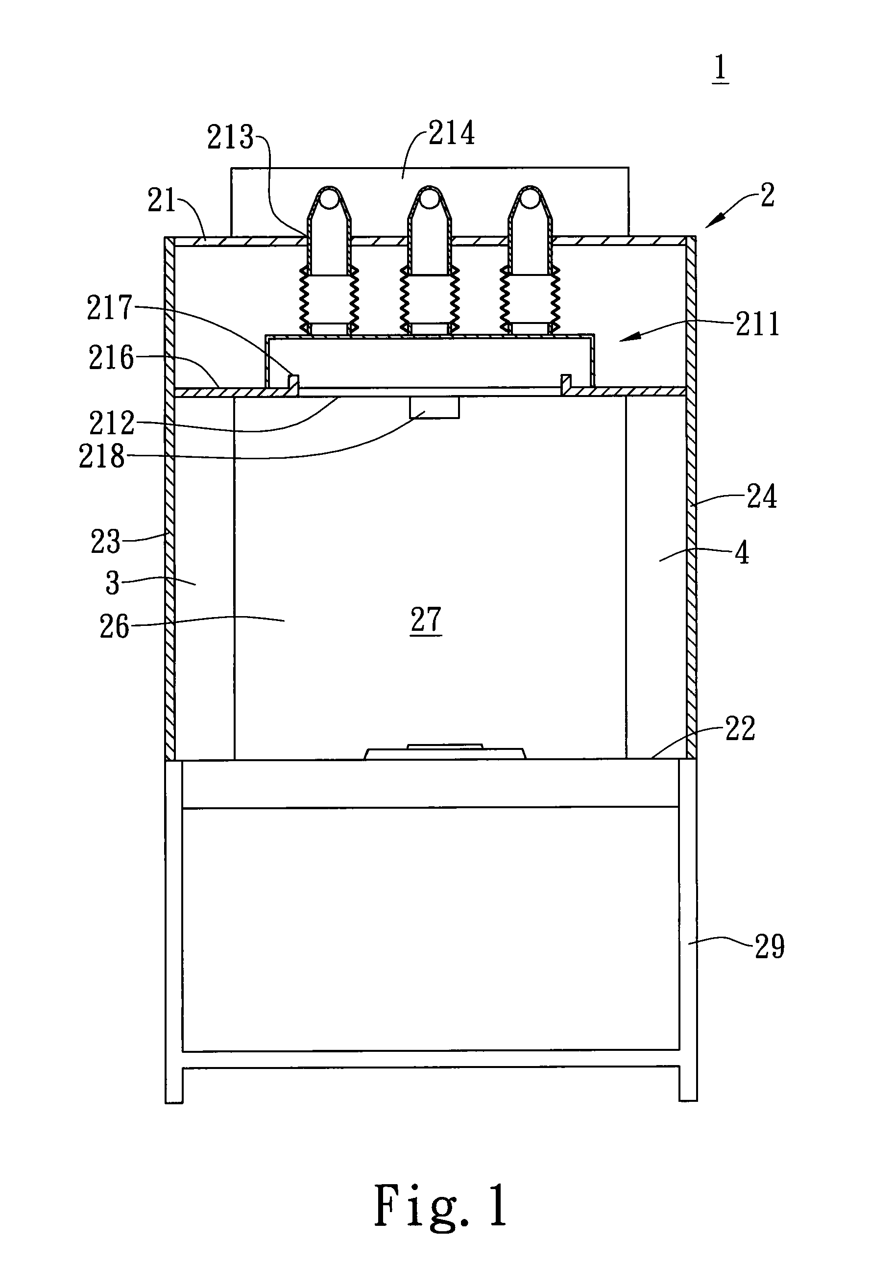
[0029]Please refer to FIGS. 1-3 showing an exhaust device having deflection plates 1, which comprises a cabinet 2, a left deflection plate 3, and a right deflection plate 4.

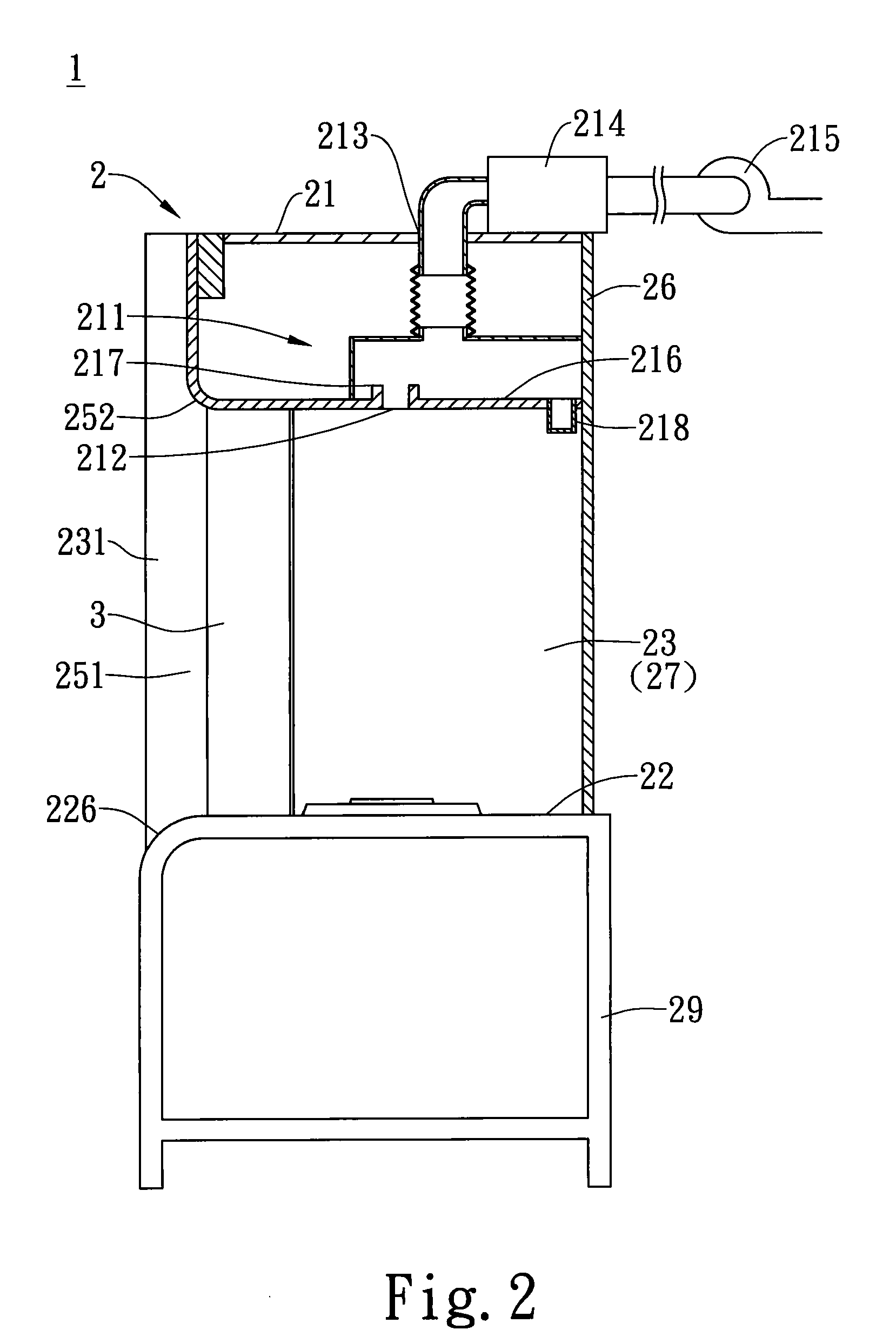
[0030]The cabinet 2 is in substantially rectangular or square shape. The lower part of the cabinet 2 is provided with a storage cabinet 29 for storage purpose. The storage cabinet 29 has legs and is able to support the cabinet 2. The cabinet 2 has an air-extraction hood 21, a bottom plate 22, a left lateral plate 23, a right lateral plate 24, and a rear plate 26. After being assembled together, above components define a space 27 within the cabinet 2. An opening 251 is provided below the front end of the air-extraction hood 21. Besides, a curved first guiding part 252 is provided at the bottom of the front end of the air-extraction hood 21, and a curved second guiding part 226 is provided at the top of the front end of the bottom plate 22. The front ends of the left lateral plate 23 and the right lateral plate 24 ...

third embodiment

[0037]Please refer to FIG. 11, in which is shown an exhaust device 1 having deflection plates. In this embodiment, a strip-shape air blow device 253 is provided at the bottom, either inside or outside the cabinet, of the front plate 25. The strip-shape air blow device 253 draws the fresh air outside the cabinet and blow the drawn air downward so as to enhance ability of preventing leakage of pollutants or high-temperature soot. In implementation, two air blow devices 253 can be provided respectively at two ends of the bottom of the front plate 25. Alternatively, as shown in FIG. 11A, when the lateral part of the front plate 25 is overlapped with a movable cabinet door 255, the air blow device 253 is provided at the bottom of the movable cabinet door 255.

fourth embodiment

[0038]Moreover, FIG. 12 shows an exhaust device 1 having deflection plates 31, 32, 41, and 42. In this embodiment, two openings 251, 253 are respectively provided in front of and in back of the cabinet 2. In other words, the two openings pass through the cabinet 2. In the space 27, a front and a rear left deflection plates 31, 32 are respectively provided in a manner of being relatively oblique to the left lateral plate 23, and a front and a rear right deflection plates 41, 42 are respectively provided in a manner of being relatively oblique to the right lateral plate 24. A first included angle θ1 is formed between the front and the rear left deflection plates 31, 32 and the left lateral plate 23. A second included angle θ2 is formed between the front and the rear right deflection plates 41, 42 and the right lateral plate 24. Besides, the front right deflection plate 41 is symmetrical to the front left deflection plate 31 while the rear right deflection plate 42 is symmetrical to th...


PUM


Abstract

An exhaust device having deflection plates comprises a cabinet that is provided with a space therein. An opening is formed in front of the cabinet. The air-extraction hood located at the top of the cabinet is provided at the bottom thereof with an elongate air-extraction slot facing downwards and parallel to the rear plate. A left deflection plate is vertically located in the space in a manner of being relatively oblique to the left lateral plate while a right deflection plate is vertically located in the space in a manner of being relatively oblique to the right lateral plate. Thereby, the air drawn towards the elongate air-extraction slot can flow into the cabinet via the left and the right deflection plates so as to prevent the leakage of pollutants from the opening in front of the cabinet.

Description

TECHNICAL FIELD[0001]The present invention relates to an exhaust device having deflection plates, and more particularly, to an exhaust device that has deflection plates used for guiding the airflow in the cabinet so as to prevent the leakage of pollutants and is suitable for the cabinets in factories and laboratories and the exhaust cabinets in commercial kitchens.BACKGROUND[0002]For performing the function of a conventional exhaust cabinet, a shelter plate with an opening is provided on the upper end of a cabinet, and a flow-guide plate is vertically placed in the rear of the cabinet, where the flow-guide plate is provided with a specially designed opening. Through the opening of the shelter plate and the opening of the flow-guide plate in the rear of the cabinet, harmful gas can be drawn out by using an air-extraction machine and ducts. When the exhaust cabinet is used, the air-extraction machine should be operated correspondingly in order to continue air extraction. During this m...

Claims


Application Information

Patent Timeline
IPC IPC(8): F24F7/00
CPCF24F9/00B01L2200/0684B08B15/023B01L1/00
Inventor HUANG, RONG FUNG
Owner HUANG RONG FUNG
Why Eureka
Try Eureka