Solar cell module

a solar cell module and module technology, applied in the direction of material gluing, electrical equipment, semiconductor devices, etc., can solve the problems of high assembly process difficulty, high assembly cost, and high assembly cost, and achieve the effect of improving the productivity of solar cell modules, controlling the thickness of adhesive layers, and simple construction

Inactive Publication Date: 2012-11-08
KYOCERA CORP
View PDF5 Cites 28 Cited by
  • Summary
  • Abstract
  • Description
  • Claims
  • Application Information

AI Technical Summary

Benefits of technology

[0008]One object of the present invention is to provide a solar cell module having a simple construction and superior productivity.
[0009]Another object of the present invention is to provide a solar cell module having a simple construction and superior load-bearing characteristics.
[0012]According to the solar cell module of the one embodiment of the present invention, because it is possible to inject the adhesive into the gap between the solar cell panel and the reinforcing member from the through hole, it is possible to adhere the reinforcing member and the solar cell panel together after mounting the reinforcing member to the holding members. For this reason, it is possible to control the thickness of the adhesive layer by the amount of adhesive injected while assembling the solar cell module, without the adhesive contaminating the other members. As a result, it is possible to improve the productivity of the solar cell module by a simple construction.
[0013]According to the solar cell module of the other embodiment of the present invention, by adopting a structure in which the mounting parts of the pair of holding members are sandwiched by the linking part of the reinforcing member, in addition to increasing the strength of the mounting parts of the holding members, it is possible to hold the reinforcing member and the holding members together securely. As a result, even if a load in a direction of either positive pressure or negative pressure acts on the solar cell panel, damage to the mounting parts of the holding members can be reduced, thereby improving the load-bearing characteristics of the solar cell module.

Problems solved by technology

However, because a large solar cell module is subjected to high wind loading and accumulated snow loading, superior load-bearing characteristics are required.
In such a configuration, if the holding by the screws is insufficient and a load is applied, there was a risk of the screws falling out.
In such a configuration, it is necessary to adjust the reinforcing member to a length that comes into contact with the wall part of the frame, and there was a risk of the assembly process becoming troublesome.

Method used


Image

  • Solar cell module
  • Solar cell module
  • Solar cell module

Examples


first embodiment

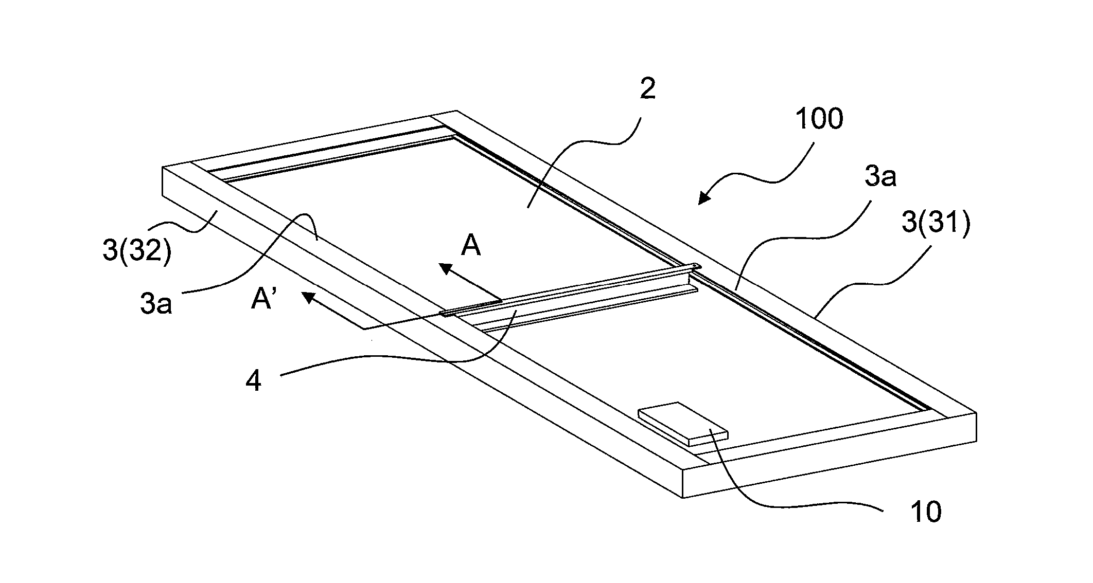
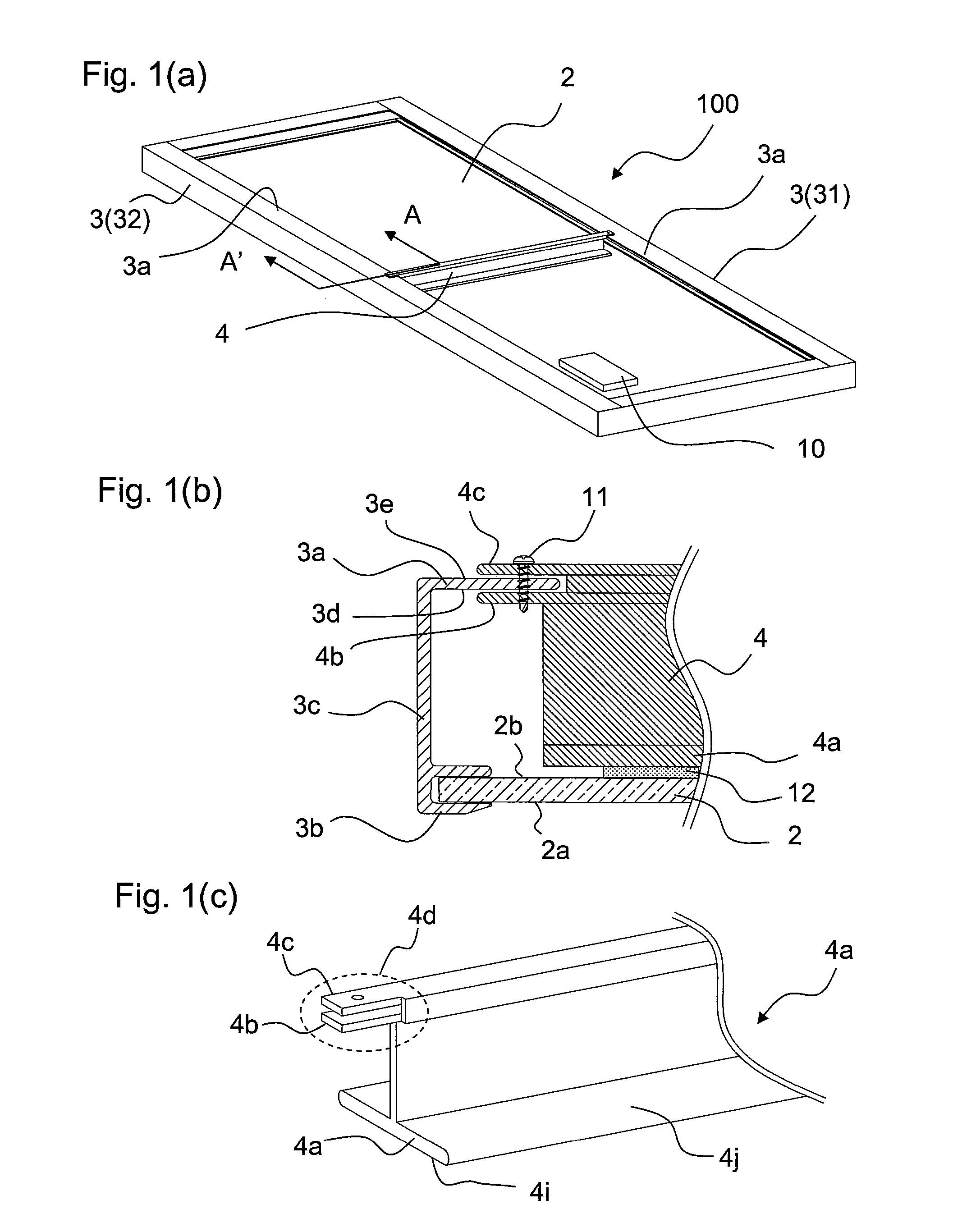
[0028]The solar cell module 100 according to the first embodiment of the present invention will be described in detail, using FIG. 1 to FIG. 3.

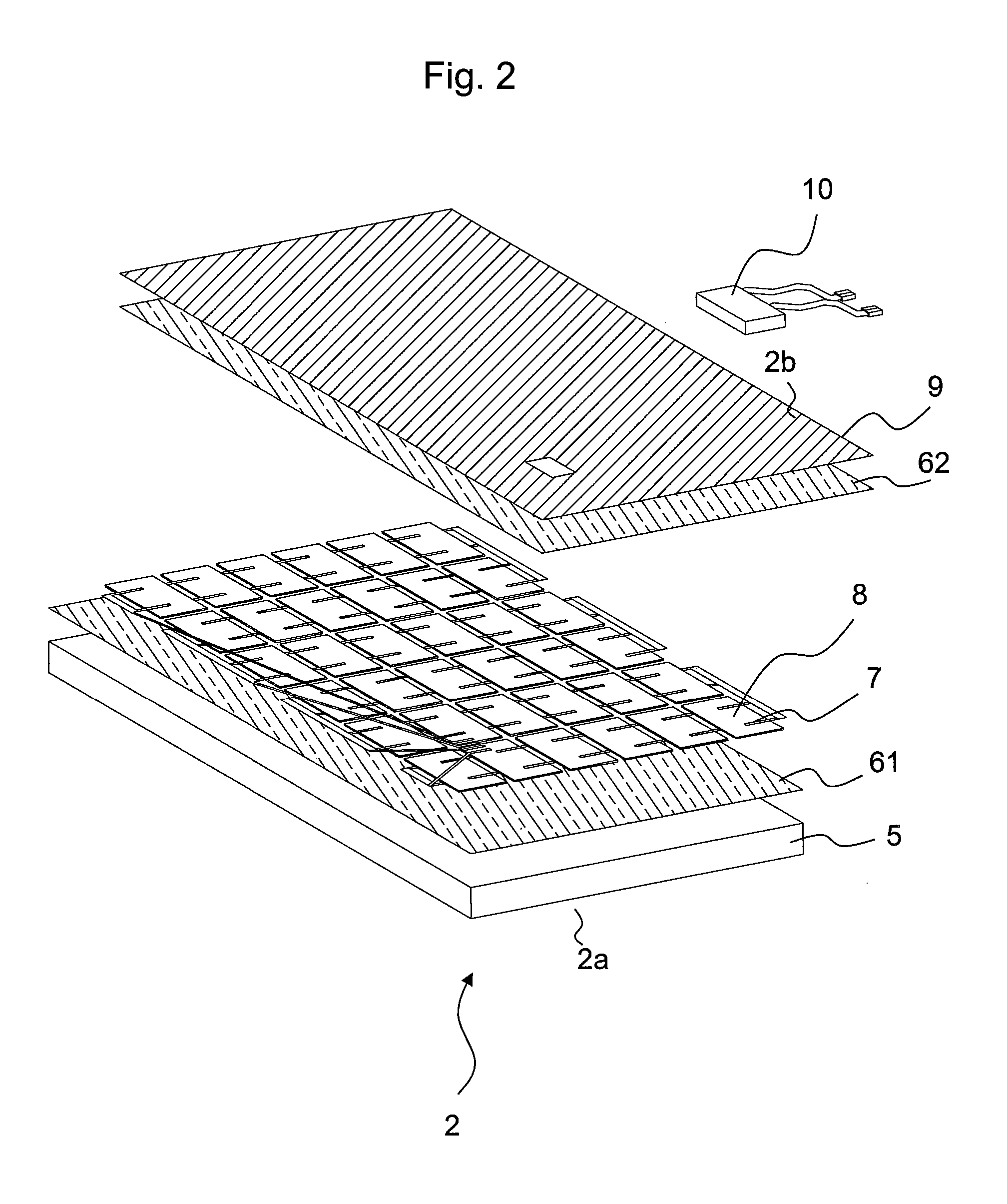
[0029]As shown in FIG. 1, the solar cell module 100 has a solar cell panel 2, a pair of holding members 3, a reinforcing member 4, and an adhesive 12. The pair of holding members 3 holds side parts at two locations on the solar cell panel 2 that are not mutually on the same side surface. The reinforcing member 4 is installed across between the pair of holding members 3. The solar cell panel 2 has a first side part and a second side part that are not mutually on the same plane. The pair of holding members 3 has a first holding member 31 holding the first side part and a second member 32 holding the second side part. In the present embodiment, as shown in FIG. 1(a), the first holding member 31 and the second holding member 32 are disposed so as to face each other. The reinforcing member 4 is linked to the holding members 3 so as to be installed...

second embodiment

[0045]Next, a solar cell module 200 according to the second of the present invention will be described in detail, using FIG. 4.

[0046]The solar cell module 200 according to the present embodiment, as shown in FIG. 4(a), differs that in from the first embodiment with respect to the form of the reinforcing member 4. Specifically, the reinforcing member 4 in the solar cell module 200 is different from the reinforcing member 4 of the first embodiment in that the second member 4c is made longer in the longitudinal direction of the reinforcing member 4 than the first member 4b.

[0047]In the present embodiment, the contact surface area between the second member 4c and the second surface 3e can be made larger than the contact surface area between the first member 4b and the first surface 3d. By this type of structure, as shown in FIG. 4(b), the reinforcing member 4 can be rotated to dispose it at a prescribed fixing position while supporting the second member 4c by the second surface 3e, tha...

third embodiment

[0048]Next, a solar cell module 300 according to the third embodiment of the present invention will be described in detail, using FIG. 5 and FIG. 14.

[0049]The solar cell module according to the present embodiment, as shown in FIG. 5(a), differs from that in the first embodiment with respect to the form of the reinforcing member 4. Specifically, the reinforcing member 4 in the solar cell module 300 differs from the reinforcing member 4 in the first embodiment in that a through hole 4e is provided in the supporting part 4a of the reinforcing member 4.

[0050]In the present embodiment, the through hole 4e is provided that passes from the first main surface 4i to the second main surface 4j. At least one part of the adhesive 12 is located within the through hole 4e. By providing such a through hole 4e, it is easy to dispose the adhesive 12 in the gap between the reinforcing member 4 and the rear-surface protective film 9 that corresponds to the non-light receiving surface 2b of the solar c...


PUM


Abstract

A solar cell module is disclosed. The solar cell module includes a solar cell panel, first and second holding members, a reinforcing member. The panel includes a light-receiving surface, a non-light receiving surface, a first side part and a second side part. The first and second holding members hold the first and second side parts respectively. The reinforcing member is laid across the first and second holding member on a non-light receiving surface side. The adhesive is disposed between the non-light receiving surface and the reinforcing member. The reinforcing member includes a supporting part that is disposed with a gap with the non-light receiving surface and that supports the non-light receiving surface via the adhesive. The supporting part includes a first main surface, a second main surface and a through hole. At least one part of the adhesive is located within the through hole.

Description

FIELD OF ART[0001]The present invention relates to a solar cell module.BACKGROUND ART[0002]One means of reducing the cost of a photovoltaic system is to increase the size of the solar cell modules. However, because a large solar cell module is subjected to high wind loading and accumulated snow loading, superior load-bearing characteristics are required.[0003]In order to improve the load-bearing characteristics, various solar cell modules including a reinforcing member supporting the center thereof have been disclosed.[0004]The Japanese Laid-open Patent Publication No. 2005-150318 discloses a solar cell module including a reinforcing member that is fitted between a solar cell panel and a frame. The reinforcing member is adhered to the rear surface of the solar cell panel with a silicone adhesive. In an arrangement such as this, because the adhesive must be coated onto the reinforcing member beforehand, high work accuracy are required to manufacturing workers.[0005]The international ...

Claims


Application Information

Patent Timeline
Patent Type & Authority Applications(United States)
IPC IPC(8): H01L31/048
CPCF16B11/006H01L31/042H02S20/00H02S30/10Y02E10/50
Inventor SUMIDA, KENICHIROITO, AKIHITOYAMASHITA, MITSUOHIRATA, HIROAKI
Owner KYOCERA CORP
Why Eureka
Try Eureka