Rain maker wildfire protection and containment system

a wildfire protection and containment system technology, applied in fire rescue and other directions, can solve the problems of insufficient protection of prior art design and methods, insufficient pressure and flow rate of fire truck pumps, so as to prevent and control the spread of wildfires, and reduce the risk of fir

Active Publication Date: 2012-11-08
HOWARD SR JOHN WAYNE
View PDF14 Cites 32 Cited by
  • Summary
  • Abstract
  • Description
  • Claims
  • Application Information

AI Technical Summary

Benefits of technology

[0015]The objects and advantages of my invention are its flexibility and mobility for rapid deployment, along with its vast operating range of several square miles of deployment at ground level or overhead both FIGS. 1 and 1a with zip line attachment. The fire protection and containment system can be moved into place by truck or helicopter and setup quickly. System Set Up is accomplished by a small task force of first responders approximately 10-40 fire fighters or smoke jumpers using both 4 wheel drive ATVs, helicopters and The Rain Maker multi purpose all terrain utility vehicle (RMATUV). The following is a snap shot of a complete system deployed over several linear miles utilizing lake water as a suppressant. Example: three hundred rain makers FIG. 1 and 1a. Fifteen 21 thousand gallon mobile storage tanks and ten 6900 gallon mobile storage tanks as depicted in FIG. 4. Ten Rain Maker all terrain utility vehicles (RMATUV), six 4 wheel drive ATVS, Pump booster manifold (not shown) support tools, forest heat resistant hose and other equipment. Ten high pressure high volume pumps as illustrated in FIG. 3, although all 10 pumps may not be required, I would have them available on or near the staging site just in case. This example could create more than one containment and protection line totaling approximately 5-10 linear miles using the layering technique and depending on terrain and topography. Additionally once the system covering 5 miles is set up and fully operational it would represent the equivalent of about 2400 virtual fire fighters-fighting at 360 degrees at each rain maker unit. However in this scenario the handful of fire fighters 20-50 that set up the 5+mile system would not be required to stay with the system or hold any of the nozzles-the system will do the job itself upon activation. This is accomplished by a remote control transmitter or other wireless device. The above described method would stop, slow down, and contain an approaching wildfire, preventing it from spreading into a at risk neighborhood. This new method of containment and protection has never been implemented or seen to my knowledge.
[0016]The system comprises a wildfire protection and containment method, and smart tools provided to first responders to assist in...

Problems solved by technology

The prior art design and method are insufficient in providing protection to homes, and creating an effective fire break or containment line in large open wildfires, for the following reasons.
Plastic or PVC pipe will quickly be compromised by radiant and convection heat generated from a large 200 foot wind driven wildfire with large fuel sources like tall trees and bushes present.
Fire truck pumps are limited in pressure and flow rates over large linear distances.
Wildfires climb trees and blow fire brands (embers) hundreds of feet into the air, this invention is confined to a ground level operation with limited flow rates by stated design, rendering it ineffective in creating a fire break in a large open wind driven wildfire event in any terrain and would be insufficient in providing adequate protection to homes or the environment.
Any pipe under high pressure will rotate, having another pipe beside it that is not permanently attached via bolting or welding does not provide stability and reliability.
Additionally any conduit system is only as reliable as its weakest link; plastic is a very w...

Method used


Image

  • Rain maker wildfire protection and containment system
  • Rain maker wildfire protection and containment system
  • Rain maker wildfire protection and containment system

Examples


Embodiment Construction

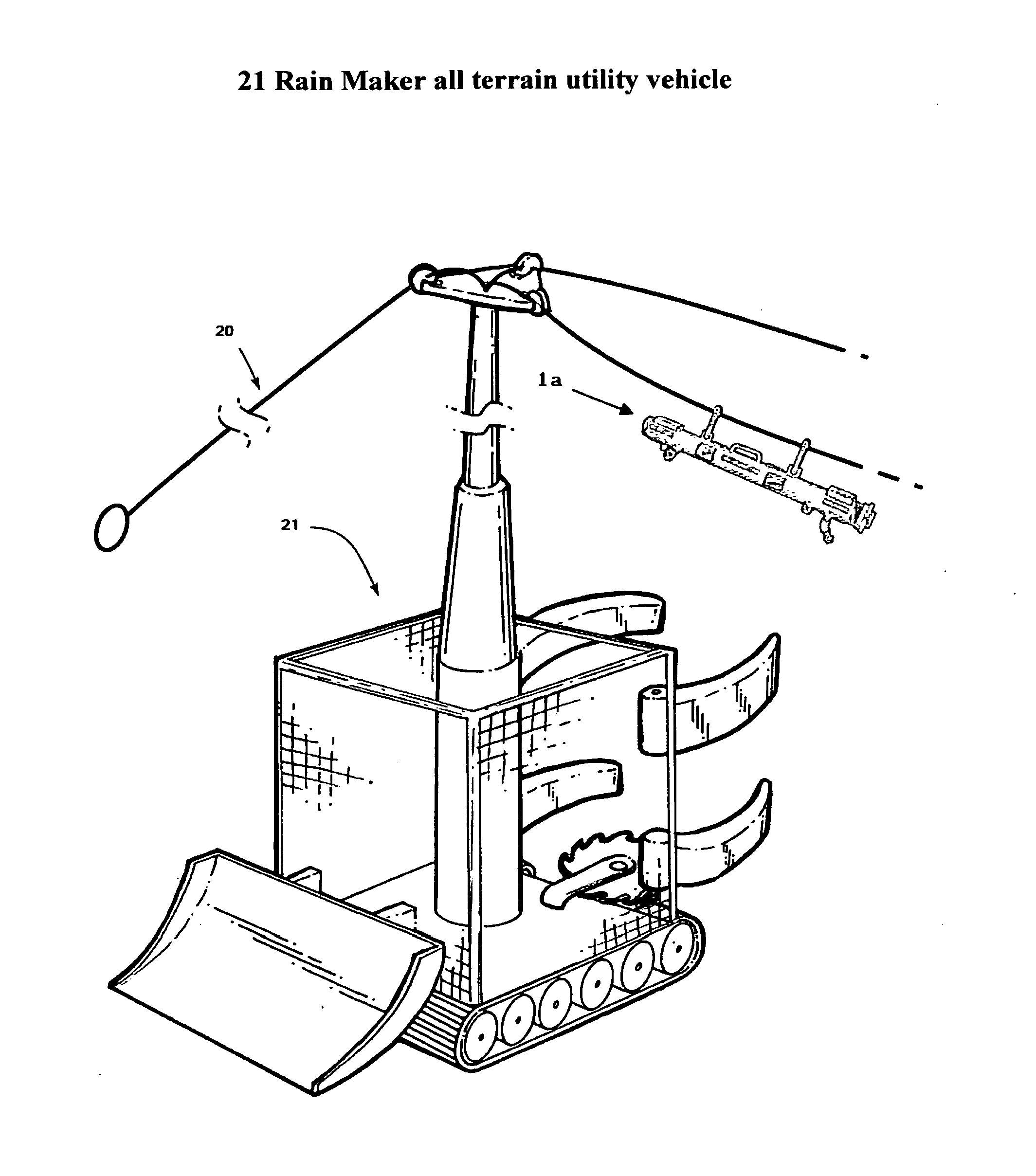
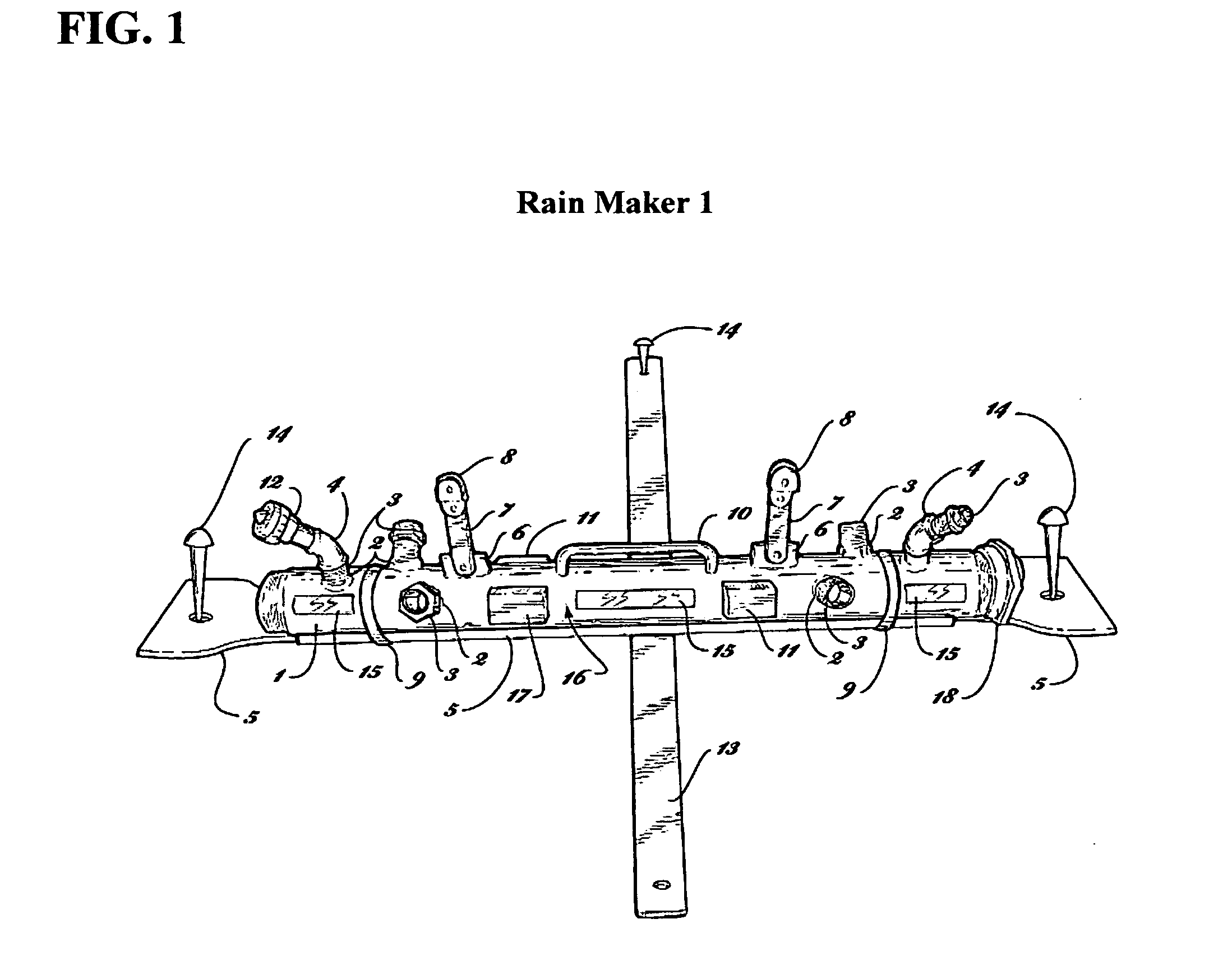
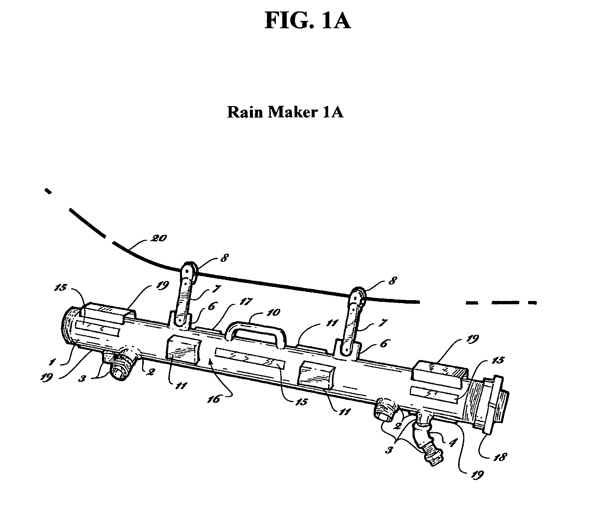
[0056]FIGS. 1 and 1a The preferred embodiment of the present invention designed for emergency first response is illustrated in FIGS. 1 and 1a (top side view). The Rain Maker pipe conduit 1 is a hollow preassembled cylindrical metal pipe of predetermined diameter and length threaded at each end to accommodate quick connect couplings and a cap on the lead unit to build pressure in the system. Holes are then cut along the longitudinal cross sections at a certain points and angles to create the 360 discharge pattern, and to allow threaded pipe fitting 2 to be inserted and welded into place on 1 and 1a. Pipe nipples 3 are then threaded into fitting 2. Fire nozzle 12 is then threaded onto all pipe nipples 3. 45 degree female elbow 4 is threaded onto pipe nipple 3 on top at each end of 1. (note 2 additional nipples will be added to top at both ends of 1 and 1a to add 2 more fire nozzles for a total of 8 on each the first responder versions not shown in drawings 1 and 1a) (Additionally an a...


PUM


Abstract

An apparatus, system and method for fire suppression and containment is provided in accordance with one embodiment of the invention. A conduit with a plurality of nozzle connections, in various configurations to create specific fire suppressant discharge patterns. Each conduit can be operated individually or connected to another conduit by a predetermined length of hose forming a contiguous system, traversing large areas of land. The invention and components form a multipurpose fire suppression apparatus. The system can be operated remotely or manually. An alternative embodiment can be installed in residential, commercial and industrial applications. Each system can be custom designed based upon environmental engineering requirements and system application-with regard to conduit diameters, material composition, shape, length and nozzle design without leaving the core design. The system components can also incorporate sensors, monitoring devices, robotics (i.e. RM all terrain vehicle) satellite imaging and wireless technology.

Description

[0001]Cross-Reference to related provisional patent application filed Sep. 5, 2009, Ser. No. 61 / 275,920 the priority date, which I claim.[0002]Not federally sponsored.FIELD OF THE INVENTION[0003]The invention relates to a self contained mobile, high tech, rapidly deployable Wildfire Protection and Containment System.BACKGROUND OF THE INVENTION[0004]The system is used as an intelligent first responder wild fire protection and containment tool in the first aspect. The new invention cost effectively controls the spread of wildfire, resulting in saving lives, homes and other commercial building structures in high risk urban wild land interface fires. The system is designed to protect entire subdivisions, cities, towns, villages and the environment from an approaching wildfire by remote operation. The robust system creates an effective contiguous suppression blanket on fuel sources and multi story building structures using new method called layering. The use of this system and methods de...

Claims


Application Information

Patent Timeline
IPC IPC(8): A62C27/00
CPCA62C3/02A62C3/0214A62C3/0292A62C3/0235A62C37/00A62C27/00A62C25/00
Inventor HOWARD, SR., JOHN WAYNE
Owner HOWARD SR JOHN WAYNE
Why Eureka
Try Eureka