Dynamic scale with multiple weighing pans, and method to operate the dynamic scale

a dynamic scale and weighing pan technology, applied in the direction of measuring devices, instruments, weighing apparatus, etc., can solve the problems of complicated calculation methods, increased space requirements, and marked increase in control expenditure and higher costs, and achieve the effect of increasing the throughput of weighed goods

Inactive Publication Date: 2012-11-08
FRANCOTYP POSTALIA
View PDF9 Cites 16 Cited by
  • Summary
  • Abstract
  • Description
  • Claims
  • Application Information

AI Technical Summary

Benefits of technology

[0012]An object of the present invention is to overcome the disadvantages of the prior art and achieve a dynamic scale with multiple weighing pans, as well as a method to increase the throughput of weighed goods.
[0025]either successfully end the weight measurement with the weighing cell of the second weighing unit, wherein the electronics of the connected weighing cell of the second weighing unit deliver a stable signal, or
[0027]By means of the second weighing pan arranged in series in the weighing path, the weighing path is extended to the required dimension in the transport direction for weighing goods of larger dimensions, for example medium-to-large format mail pieces. By shortening the weighing pan of the first weighing unit in connection with the adjacent weighing pan of the second weighing unit (on whose weighing cell the weighing cell of the first weighing unit is arranged), a markedly shorter weighing good interval can be achieved for small-format mail pieces, and thus a markedly higher weighing good throughput without increasing the system speed (even for mixed mail).
[0028]The solution can advantageously be realized without significant effort in the same structural space which is required by the previously used dynamic scale of the Centormail franking machine.
[0036]Due to the cascading arrangement of the weighing cells and the active direction of gravity, the weight values measured by the individual weighing units do not need to be offset with one another via complicated calculation methods. Depending on the delivery of a stable signal from the weighing cells during the transport of the weighed good in the transport direction, a switching respectively takes place of an evaluation of the measurement values that originate from one weighing unit to those measurement values that originate from an additional weighing unit whose weighing cell delivers a stable signal.

Problems solved by technology

However, additional devices to separate and merge the mail flow before and after the scale are necessary for this, which increases the space requirement.
The parallel arrangement of two weighing units brings with it the problem of the markedly increased space requirement due to the two units to control the mail flow, a markedly increased control expenditure and higher costs.
In this method, the weighing signals of the weighing units must be coupled with one another and complicated calculation methods are used since a portion of the weight of the weighed good is distributed among the respective weighing units.
The higher cost relative to a system with only a single weighing unit is disadvantageous.
The arrangement of multiple weighing units in series makes a markedly increased computing cost necessary in the calculation of the weight values, which can be time-critical.
Slippage / synchronization programs can occur between the weighing units, which can lead to impacts that affect the weighing result.
When the dynamic scale is used as a peripheral device for a franking system, the franking system limits the transport speed of a mail piece.
An increase of the system speed is not possible, or is possible within very narrow, very precisely considered limits.
Additional limitations also result from the processing times, for example the calculation speed, and the billing time for franking imprints in the dynamic weighing mode of the Centormail® franking system.

Method used


Image

  • Dynamic scale with multiple weighing pans, and method to operate the dynamic scale
  • Dynamic scale with multiple weighing pans, and method to operate the dynamic scale
  • Dynamic scale with multiple weighing pans, and method to operate the dynamic scale

Examples


Embodiment Construction

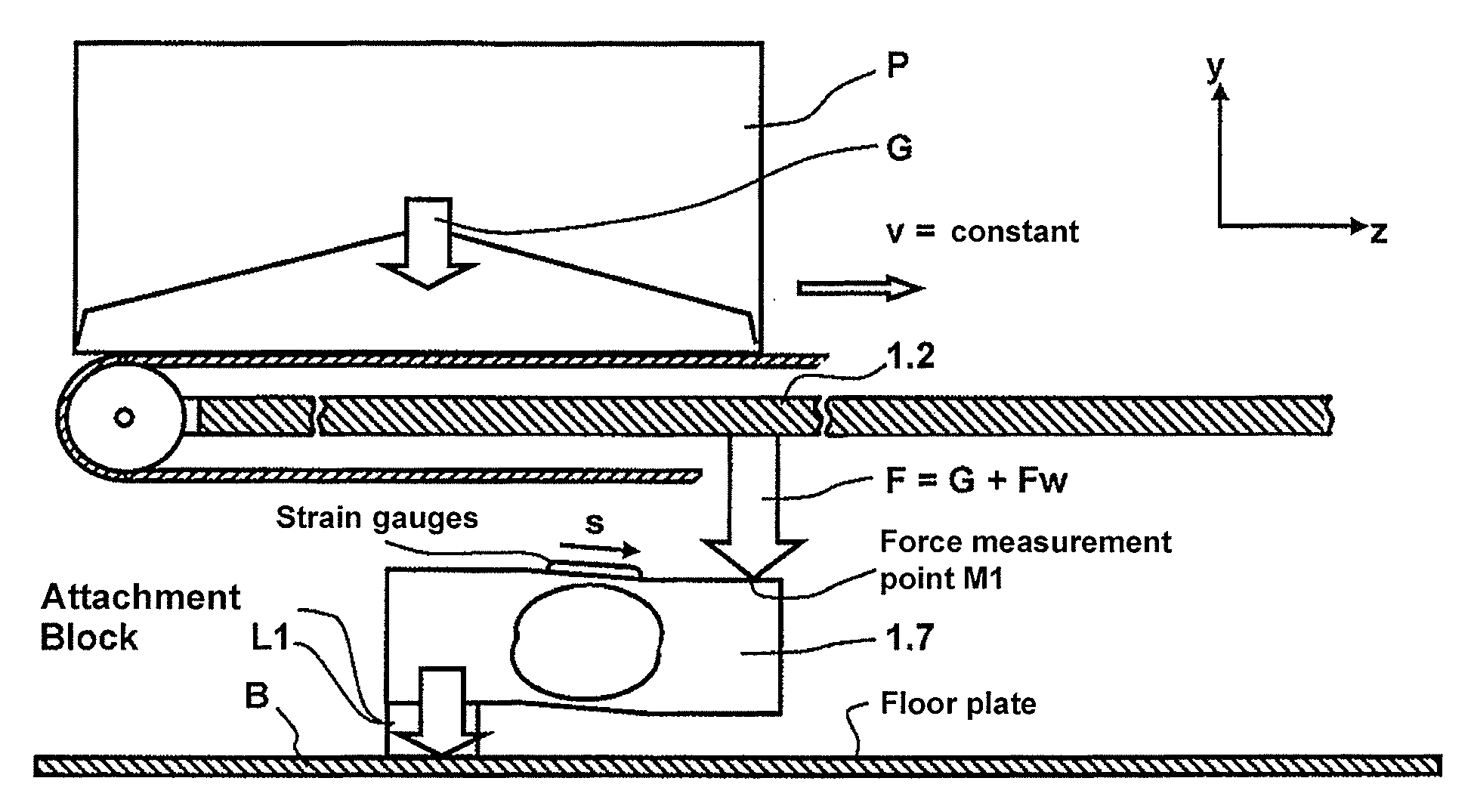
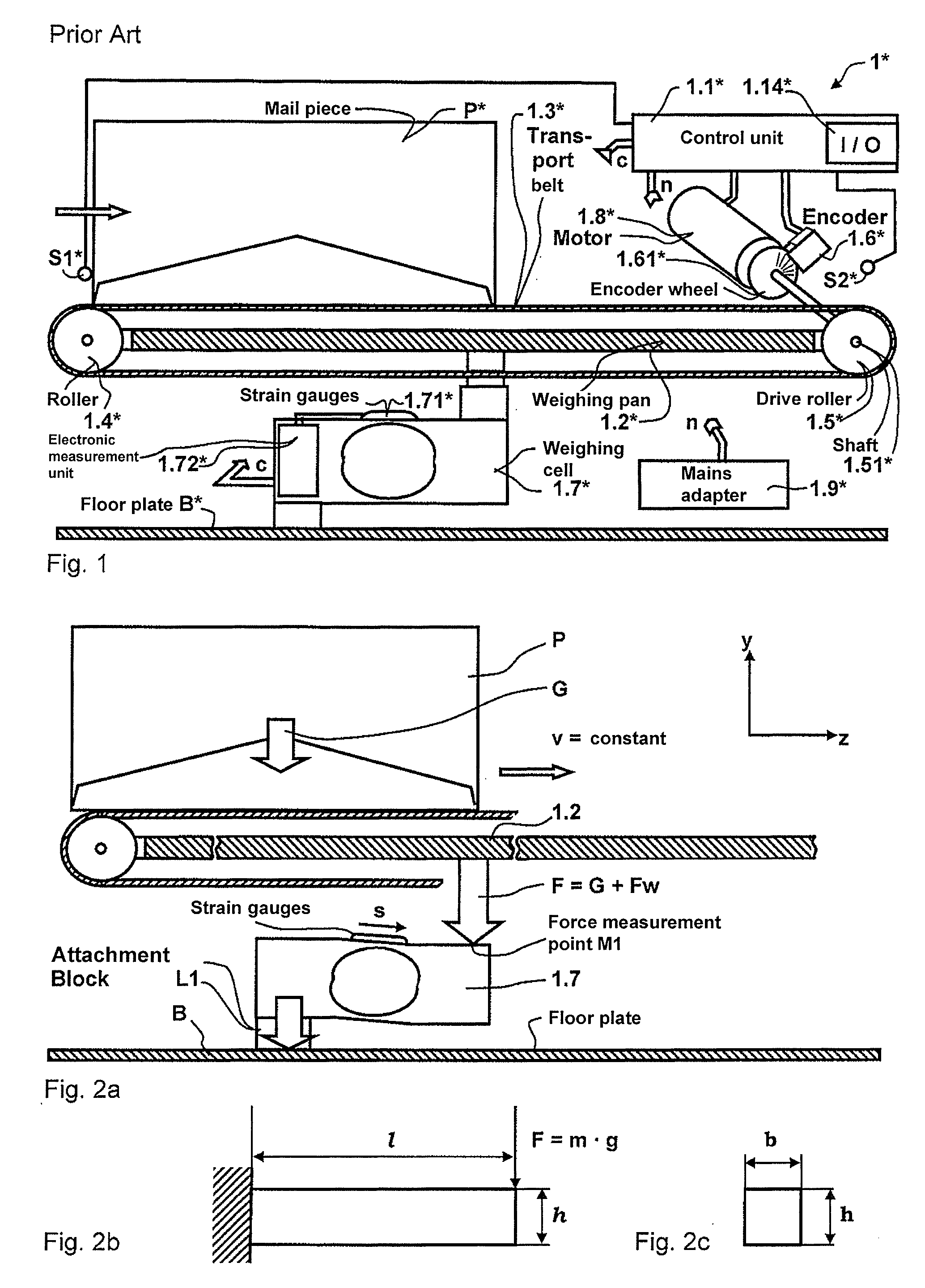
[0072]Shown in FIG. 1 is a simplified representation of a known dynamic scale 1*, which is commercially available from Francotyp-Postalia for use together with a Centormail® franking machine in a mail processing system that is suitable for mixed mail and in which flat goods being weighed (mail pieces) are supplied standing on edge. A controller 1.1* of the dynamic scale 1* has an input / output interface 1.14* and can be connected via the latter with a franking machine (not shown). The controller 1.1* is connected in terms of control with a first sensor S1*, with a second sensor S2*, with an encoder 1.6*, with an electronic measurement unit 1.72* of a weighing cell 1.7*, and with a motor 1.8*, and is supplied from a mains adapter 1.9*. The weighing cell 1.7* has strain gauges 1.71* that are electrically connected with the electronic measurement unit 1.72*. A mail piece P* standing on edge and supplied in the transport direction z arrives on a transport belt 1.3* and is transported fur...


PUM


Abstract

A dynamic scale has multiple weighing units, each equipped with a weighing cell and a weighing pan, the weighing pan lying in an upper plane and the weighing cell between a lower plane spaced from the upper plane in the direction of gravity. A transport device has a motor encoder and sensors, with the encoder and sensors being electrically connected with the inputs of a control unit. The multiple weighing units are serially adjacent in a transport path, with simultaneous cascaded arrangement of the weighing cells in the direction of gravity. The control unit simultaneously starts the weighing processes in all weighing cells in a dynamic weighing mode and controls a transport motor depending on signals of the sensors and the encoder and controls the dynamic scale depending on signals from the weighing cells.

Description

BACKGROUND OF THE INVENTION[0001]1. Field of the Invention[0002]The invention concerns a dynamic scale with multiple weighing pans and a method to operate such a dynamic scale. The invention allows an increased throughput of products of different dimensions that are to be weighed, in particular of unit loads to be weighed (for example of mail pieces and other shipments) but also of weighed goods which have no permanent, fixed dimensions. The invention is suitable for use in weighing systems, in franking systems with dynamic scales, or in mail systems of different delivery services, mail carriers and shippers which have a dynamic scale.[0003]2. Description of the Prior Art[0004]From EP 20 65 686 A1 (=US 2009 / 0139777 A1), a parallel arrangement of two weighing units is known in which the throughput can be increased via parallelization of the weighing process. However, additional devices to separate and merge the mail flow before and after the scale are necessary for this, which increa...

Claims


Application Information

Patent Timeline
Patent Type & Authority Applications(United States)
IPC IPC(8): G01G19/00
CPCG01G19/005G01G21/23G01G21/22
Inventor HUEBLER, UWEKIESER, AXELSCHLAAFF, TORSTEN
Owner FRANCOTYP POSTALIA
Why Eureka
Try Eureka