Method and apparatus for treating natural gas and oil well drilling waste water

a technology for natural gas and oil wells, applied in the nature of treatment water, multi-stage water/sewage treatment, separation processes, etc., can solve the problems of limiting the ability to dispose of or treat this water by conventional means, unsuitable for reuse, and high cost of disposal of water and organically contaminated solids contained therein, so as to improve chemical efficiency and performance.

Inactive Publication Date: 2012-11-08
ADDLEMAN ENTERPRISES +1
View PDF7 Cites 22 Cited by
  • Summary
  • Abstract
  • Description
  • Claims
  • Application Information

AI Technical Summary

Benefits of technology

[0024]The product water from the instant process is a sodium chloride (brine) solution, which is suitable for reuse as a portion of the makeup water in drilling operations or hydrofracturing operations. The instant process may include an ozone treatment

Problems solved by technology

The contaminants in this water render it unsuitable for reuse except in small proportions.
Disposal of the water and the organically contaminated solids contained therein has become an expensive proposition for the well developers and also a difficult environmental problem.
New environmental regulations, as well those proposed and likely to be implemented, may severely limit the ability to dispose of or treat this water by conventional means within the states of Pennsylvania and New York as well as Texas, and Idaho among others, and some foreign countries.
Alternatively, previous disposal of the pit water has been accomplished by transport to and subsequent treatment at conventional municipal waste water treatment facilities and specialized industrial treatment facilities, provided that the drilling muds utilized are “water based.” New and pending regulations may severely limit this option.
“Oil based” drilling mud may not be treated in significant quan

Method used


Image

  • Method and apparatus for treating natural gas and oil well drilling waste water
  • Method and apparatus for treating natural gas and oil well drilling waste water
  • Method and apparatus for treating natural gas and oil well drilling waste water

Examples


Embodiment Construction

[0032]The present invention will be described in connection with certain preferred embodiments. However, it is to be understood that there is no intent to limit the invention to the embodiments described. On the contrary, the intent is to cover all alternatives, modifications, and equivalents as may be included within the spirit and scope of the invention as defined by the appended claims.

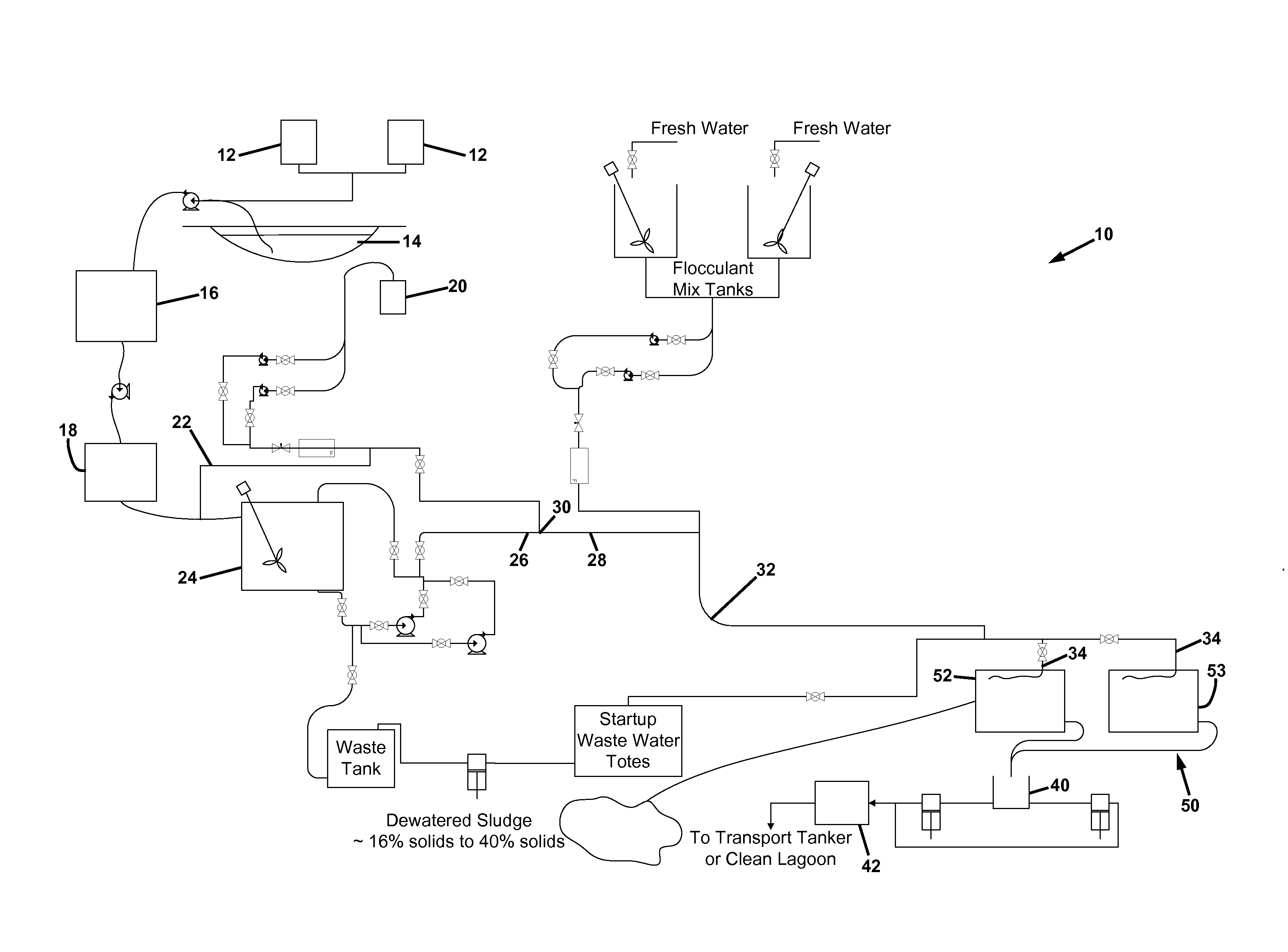
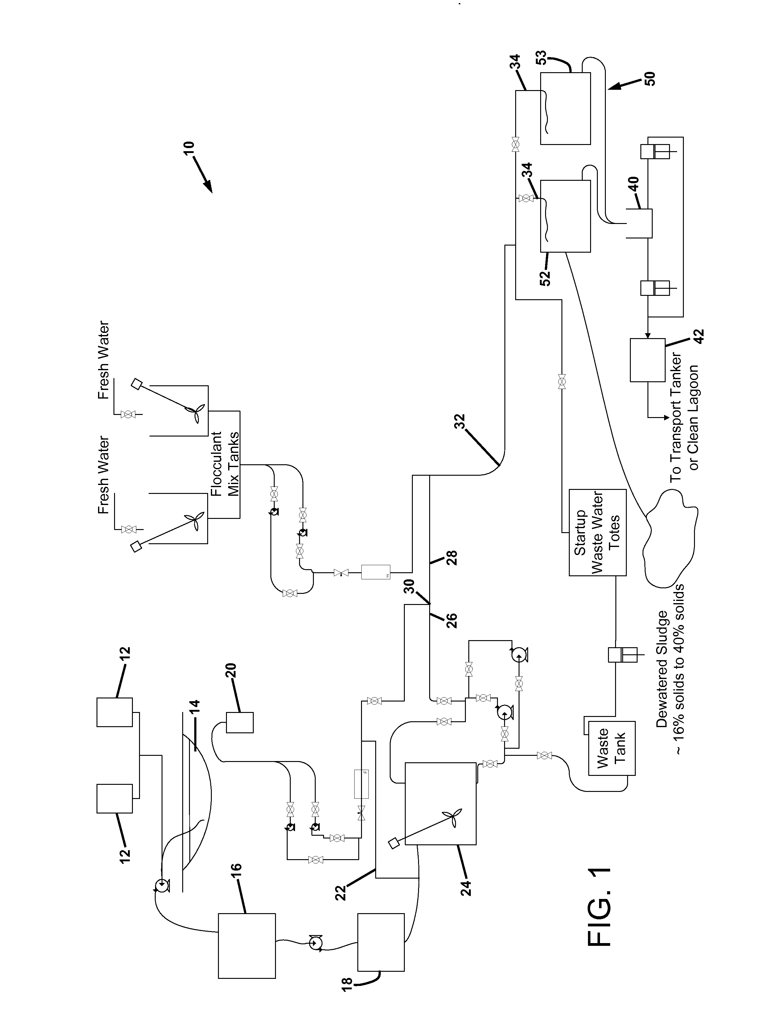
[0033]For a general understanding of the present invention, reference is made to the drawings. In the drawings, like reference numerals have been used throughout to designate identical elements. It is to be understood that the labeling of the vessels, conduits, pumps, filters, and other process equipment with dimensions, volumes, flow rates, capacities, materials of construction, and other specifications is meant to be exemplary only, and not limiting with respect to the instant apparatus and method. The apparatus and method may be operated in many other suitable configurations within the scope of ...


PUM

PropertyMeasurementUnit
Particle sizeaaaaaaaaaa

Abstract

A method of treating contaminated water effluent from a well drilling operation. The method comprises decomposing organic contaminants in the effluent by bubbling a gas containing ozone through the effluent; adding a coagulant to increase the particle size of solid particles contained in the effluent; adding a flocculant to increase the particle size of solid particles contained in the effluent, thereby forming flocs suspended in the effluent; and filtering the flocs from the effluent to produce a filtrate and flocculated solids. The method may further comprise adding the coagulant into a stream of effluent flowing within a first conduit under controlled shear conditions, and adding the flocculant into a stream of effluent containing pin flocs flowing within a second conduit under controlled shear conditions. The method may further comprise delivering the effluent containing the suspended flocs into a filter through a conduit floating in the effluent contained in the filter.

Description

CROSS-REFERENCE TO RELATED PATENT APPLICATIONS[0001]This application claims priority from U.S. Provisional Patent Application No. 61 / 481,370 filed May 2, 2011, the disclosure of which is incorporated herein by reference. This invention is also related to the inventions disclosed in U.S. patent application Ser. No. 12 / 914,072 filed Oct. 28, 2010, and U.S. Provisional Application for Patent No. 60 / 255,504, filed Oct. 28, 2009, the disclosures of which are incorporated herein by reference.BACKGROUND[0002]1. Technical Field[0003]This invention relates to the removal of contaminants from waste water discharged at a gas wellhead, and more particularly to the removal of contaminants from drilling water that is used during the process of drilling a well bore, and that is subsequently discharged from the wellhead. The waste water may contain petroleum-based drilling muds. The waste water may be treated as it is discharged from a well bore, or after it is temporarily stored in a nearby lagoon...

Claims


Application Information

Patent Timeline
IPC IPC(8): C02F1/52
CPCC02F1/52C02F1/001C02F1/78C02F2201/008C02F9/00C02F2101/30C02F2103/365C02F5/02
Inventor MILLER, FRANCIS C.ADDLEMAN, STEVEN B.
Owner ADDLEMAN ENTERPRISES
Why Eureka
Try Eureka