
Black organic light-emitting diode device

a light-emitting diode and organic technology, applied in the manufacture of electrode systems, electric discharge tubes/lamps, discharge tubes luminescnet screens, etc., can solve the problems of reducing contrast and visibility, affecting the photoefficiency of the device, so as to reduce the reflection of external light, reduce the thickness of the device, and improve the effect of photoefficiency

Active Publication Date: 2012-11-08
INVENTION INVESTMENT IRELAND LLC
View PDF2 Cites 33 Cited by
  • Summary
  • Abstract
  • Description
  • Claims
  • Application Information

AI Technical Summary

Benefits of technology

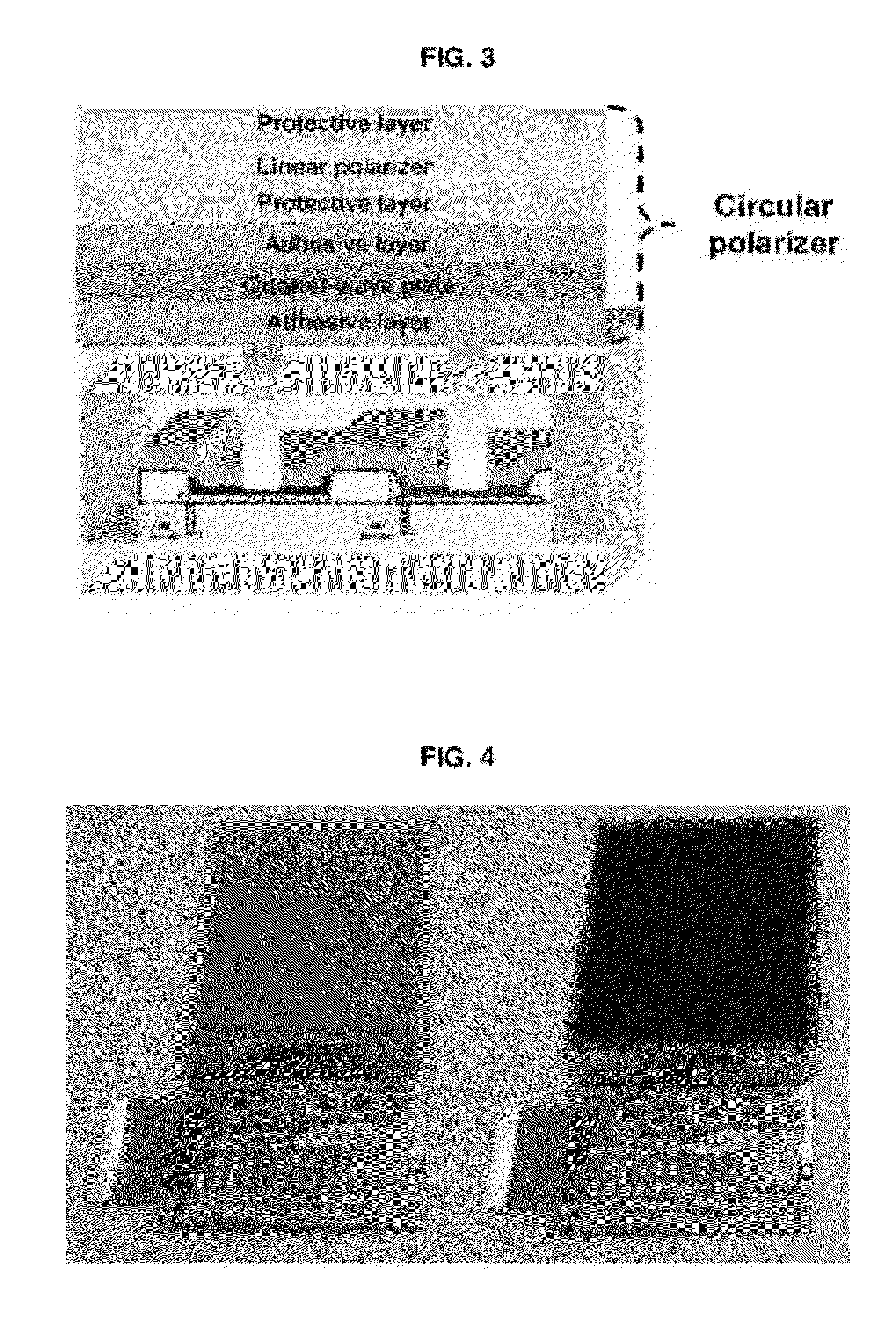
[0011]Accordingly, the present invention has been made keeping in mind the above problems occurring in the related art, and an object of the present invention is to provide a black organic light-emitting diode device, in which an organic light-emitting diode is simply configured by removing a circular polarizer used conventionally to absorb external light to increase contrast of the device, and which may solve problems of high process costs and low photoefficiency, which are mainly caused by the use of the circular polarizer.
[0012]Another object of the present invention is to provide a black organic light-emitting diode device, which does not affect light emission efficiency because the reflectance of a bottom metal layer positioned adjacent to a light-emitting layer is not decreased, and in which additional metal-dielectric thin layers are inserted outside the device without the need to adjust the thickness of an organic layer and a transparent electrode layer and are controlled to form a resonant absorbing configuration, so that the reflection of external light may be reduced and photoefficiency may be improved without any influences on the electrical properties of the device.

Problems solved by technology

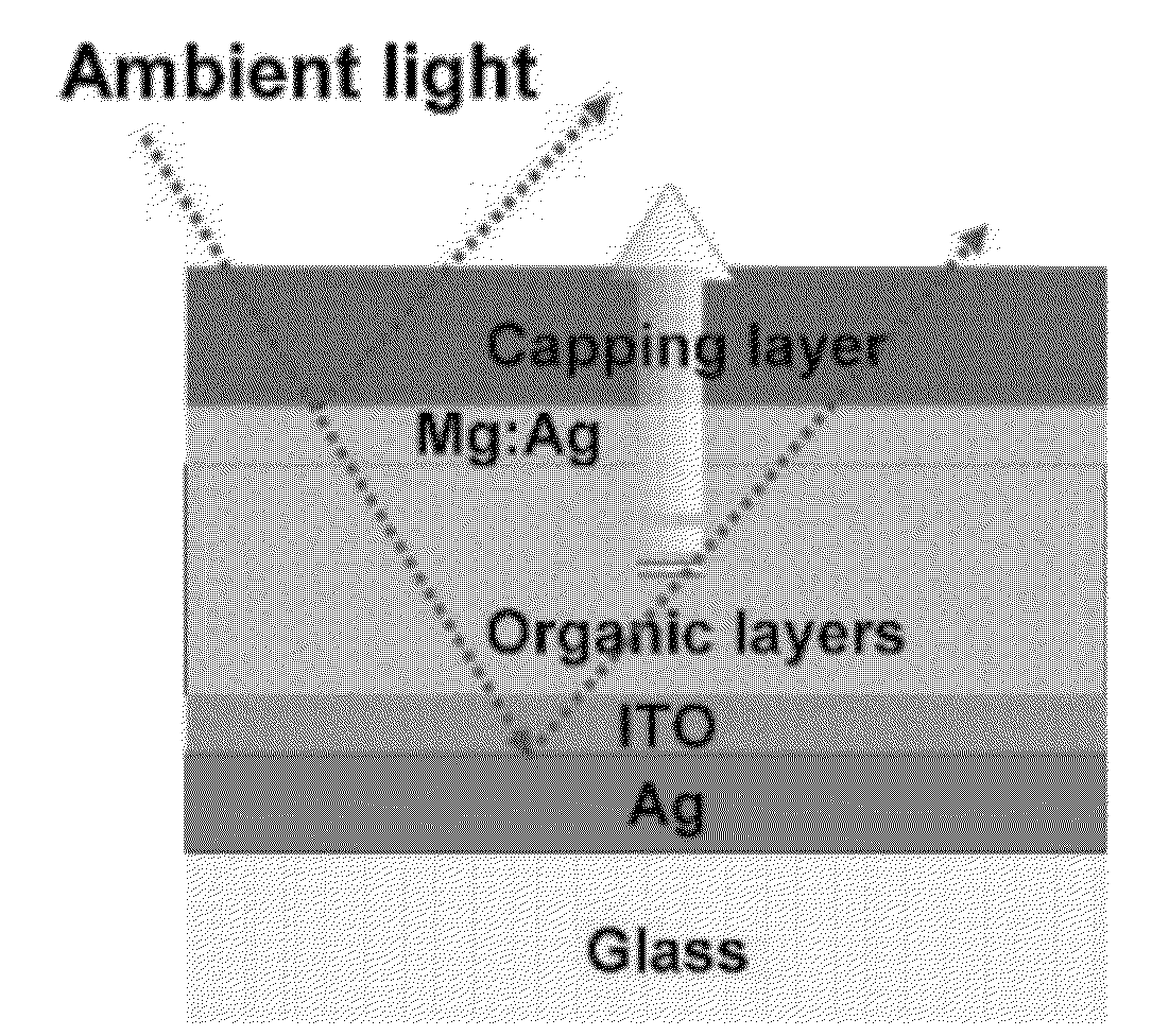
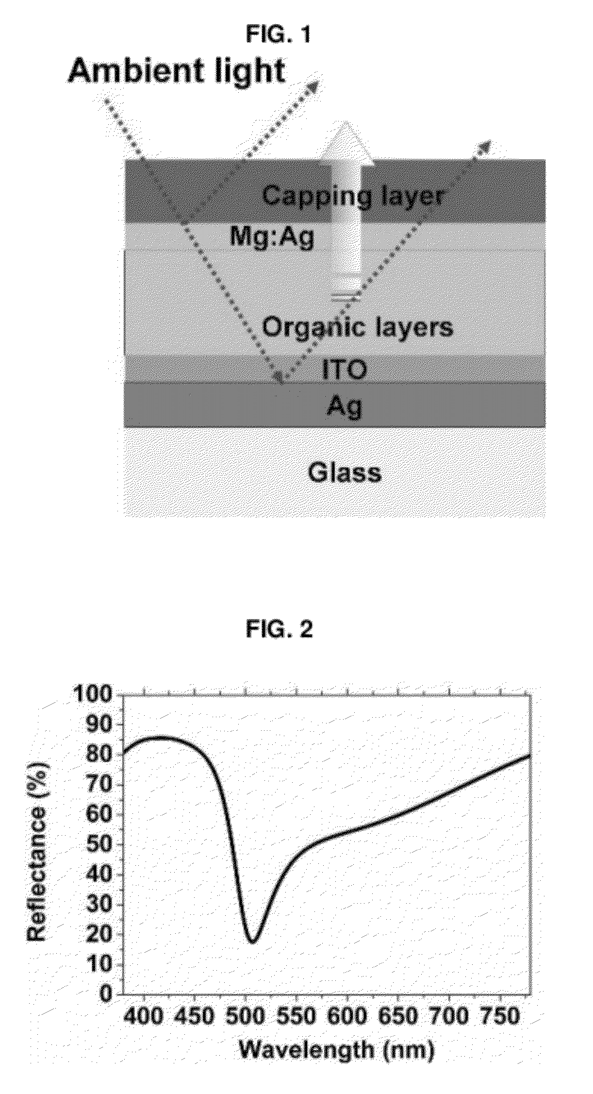
In the case where a user sees an image outdoors using a flat panel display, sunlight is reflected from the display undesirably lowering contrast and visibility.
Particularly, the case of an organic light-emitting display is problematic because such reflection from a metal reflective film is much more severe.
The case where this polarizer is applied to an ultrathin display which is the most recent trend is problematic because it may increase the thickness of the display and is also disposed outside the device thus requiring an additional process and making it difficult to form an integrated single device.
However, because the conventional configurations as above may decrease the reflectance of the metal electrode positioned under the light-emitting layer, light emitted downwards from the light-emitting layer is not reflected but is reduced, undesirably decreasing photoefficiency.
Also, as the reflectance of the bottom metal layer positioned adjacent to the light-emitting layer decreases, a microcavity phenomenon may decrease undesirably lowering luminance.
Hence, the above technique is difficult to apply to actual devices because of influences on the electrical properties.

Method used


Image

  • Black organic light-emitting diode device
  • Black organic light-emitting diode device
  • Black organic light-emitting diode device

Examples


example 1

[0087]Cr was used as a second metal layer 70, and SiO2 was used as both a phase matching layer (a first interlayer 60) and a phase compensation layer (a second interlayer 80). In the present invention, a transfer matrix type was adopted, which was adapted for reflection and transmission of a thin layer configuration. Such a transfer matrix type suitable for use in many optical coating and optical filter designs was described well in “Thin-Film Optical Filter, 3rd ed.” by Macelod.

[0088]FIG. 9 illustrates the external light reflectance depending on changes in the thickness of the phase matching layer (the first interlayer 60) and the phase compensation layer (the second interlayer 80). FIG. 14 illustrates changes in reflection of external light depending on the thickness of the phase matching layer (the first interlayer 60). In the drawing, the parenthesized numerals indicate luminous reflectance values, and the smallest reflectance is obtained when SiO2 is 60 nm. FIG. 15 illustrates ...

example 2

[0089]When Cr was used as the second metal layer 70 and SiO2 was used as the phase matching layer (the first interlayer 60) and the phase compensation layer (the second interlayer 80), results depending on changes in thickness of the second electrode 50 using Mg:Ag were analyzed.

[0090]FIGS. 18 and 19 are graphs illustrating the external light reflectance and the efficiency depending on changes in the thickness of the second electrode 50. In Example 1, the thickness of the second electrode 50 was 18 nm which is the same as in the conventional OLED. As such, the external light reflectance was about 2.9%, and the efficiency was improved by about 3% compared to the conventional OLED.

[0091]However, as the thickness of Mg:Ag which is the second electrode 50 decreases, the efficiency is improved and the external light reflectance is increased. At about 16 nm, the external light reflectance is 3.7% and the efficiency is improved by about 26%.

[0092]The thickness of the Mg:Ag electrode can be...

example 3

[0093]Cr was used as a second metal layer 70, and SiNx was used as a phase compensation layer (a second interlayer 80) and a phase matching layer (a first interlayer 60).

[0094]FIGS. 20 and 21 are graphs illustrating the external light reflectance and the efficiency when the thickness of the phase compensation layer (the second interlayer 80) made of SiNx is 60 nm and the thickness of Cr is 10 nm. For example, when the thickness of the phase matching layer (the first interlayer 60) is 50 nm, the external light reflectance is about 4.8%, and the efficiency is improved by about 2%.


PUM


Abstract

The present invention relates to a black organic light-emitting diode that implements a resonant absorbing configuration, the black organic light-emitting diode comprising: a glass substrate; a first metal layer formed on the glass substrate; a first electrode formed on the first metal layer; an organic light-emitting layer formed on the first electrode; a second electrode formed on the organic light-emitting layer, opposite the first electrode; a first interlayer formed on the second electrode; a second metal layer formed on the first interlayer; and a second interlayer formed on the second metal layer, wherein by controlling the thickness of the first interlayer and the second interlayer, external light reflected by the first metal layer and the second electrode destructively interferes with light reflected by the second metal layer.

Description

REFERENCE TO RELATED APPLICATIONS[0001]This is a continuation of pending International Patent Application PCT / KR 2010 / 005060 filed on Jul. 30, 2010, which designates the United States and claims priority of Korean Patent Application No. 10-2009-0106496 filed on Nov. 5, 2009, the entire contents of which are incorporated herein by reference.FIELD OF THE INVENTION[0002]The present invention relates to a black organic light-emitting diode device using a resonant absorbing configuration with improved contrast and photoefficiency.BACKGROUND OF THE INVENTION[0003]Recently, displays are being replaced with portable thin flat panel displays. Among the flat panel displays, an organic light-emitting diode (OLED) display which spontaneously emits light has a wide viewing angle, high contrast and fast response rate and is thus receiving attention as a next-generation display, and is also advantageous because of superior luminance, driving voltage and response rate and a wide color reproduction ...

Claims


Application Information

Patent Timeline
Patent Type & Authority Applications(United States)
IPC IPC(8): H05B33/14H05B33/10H05B33/28
CPCH01L51/5281H10K50/86H10K50/865
Inventor LEE, YONG-HEECHO, SANG-HWANDO, YOUNG RAG
Owner INVENTION INVESTMENT IRELAND LLC
Learn More