Ferrite phase shifter and automatic matching apparatus

a phase shifter and automatic matching technology, applied in the direction of delay lines, electrical devices, waveguides, etc., can solve the problems of heat generation and consequent degradation of the function of the phase shifter, and achieve the effects of reducing radiation resistance, high cooling effect, and suppressing accumulation of hea

Active Publication Date: 2012-11-08
NIPPON KOSHUHAKK
View PDF6 Cites 2 Cited by
  • Summary
  • Abstract
  • Description
  • Claims
  • Application Information

AI Technical Summary

Benefits of technology

[0020]In addition to the configurations described above and configurations of embodiments of the invention, the scope of the invention disclosed in this specification includes partial substitutions between the inventive configurations, combinations of the inventive configurations, and configurations representing superordinate concepts of the invention obtained by deleting parts of the inventive configurations within a limit in which partial effects of the invention can be achieved.
[0021]In a ferrite phase shifter and an automatic matching apparatus according to the invention, ferrites have a substantially sheet-like shape which suppresses accumulation of heat. The substantially sheet-like ferrites are disposed in tight contact with inner walls of wide surfaces of a rectangular waveguide to reduce resistance to radiation. Thus, heat generated at the ferrites can be smoothly released through the walls of the rectangular waveguide, and a high cooling effect can be achieved. Therefore, a temperature rise at the ferrites can be suppressed to maintain the characteristics of the ferrites even when they are used at a high power, and the phase shifter can stably demonstrate high performance.
[0022]When the substantially sheet-like ferrites are formed by arranging a plurality of ferrite pieces with some gaps left between them, the generation of a great thermal stress at the substantially sheet-like ferrites can be prevented by a difference between the expansion coefficients of the rectangular waveguide and the ferrites. Thus, the ferrites can be prevented from cracking.
[0023]When dielectric layers are provided on the surfaces of the substantially sheet-like ferrites facing each other, an electromagnetic field distribution generated in the rectangular waveguide can be concentrated at the ferrites to increase the electromagnetic field intensity of a high frequency wave in the region of the ferrites. Thus, the rate of a phase change caused by the ferrites can be improved.
[0024]When yokes are provided in positions substantially corresponding to the position of the substantially sheet-like ferrites on the outer walls of the wide surfaces of the rectangular waveguide, magnetic circuits are formed by the ferrites and the yokes. The magnetic circuits allow the amount of a current flowing through the coil to be reduced or allow the number of turns of the coil to be reduced.
[0025]At least one pair of holes having a structure to serve as a cut-off for a propagating high frequency wave is provided at both ends of the substantially sheet-like ferrites in the longitudinal direction of the rectangular waveguide. A ferrite different from the substantially sheet-like ferrites is provided in each of the holes. Inner ends of the other ferrites are connected to the substantially sheet-like ferrites, and outer ends of the other ferrites are connected to each other through the yokes. Thus, magnetic circuits are formed by the substantially sheet-like ferrites, the other ferrites and yokes. It is therefore possible to reduce the amount of a current flowing through the coil or the number of turns of the coil. It is also possible to improve response of a variable magnetic field to the rate of a time-varying change in a control current passed through the coil.

Problems solved by technology

When a voltage input to a ferrite phase shifter becomes too high, heat is generated because of increased loss at the ferrite.
Such a temperature rise of the ferrite results in significant changes in characteristics of the ferrite, and the function of the phase shifter can be consequently degraded.

Method used


Image

  • Ferrite phase shifter and automatic matching apparatus
  • Ferrite phase shifter and automatic matching apparatus
  • Ferrite phase shifter and automatic matching apparatus

Examples


first embodiment

[Ferrite Phase Shifter of First Embodiment]

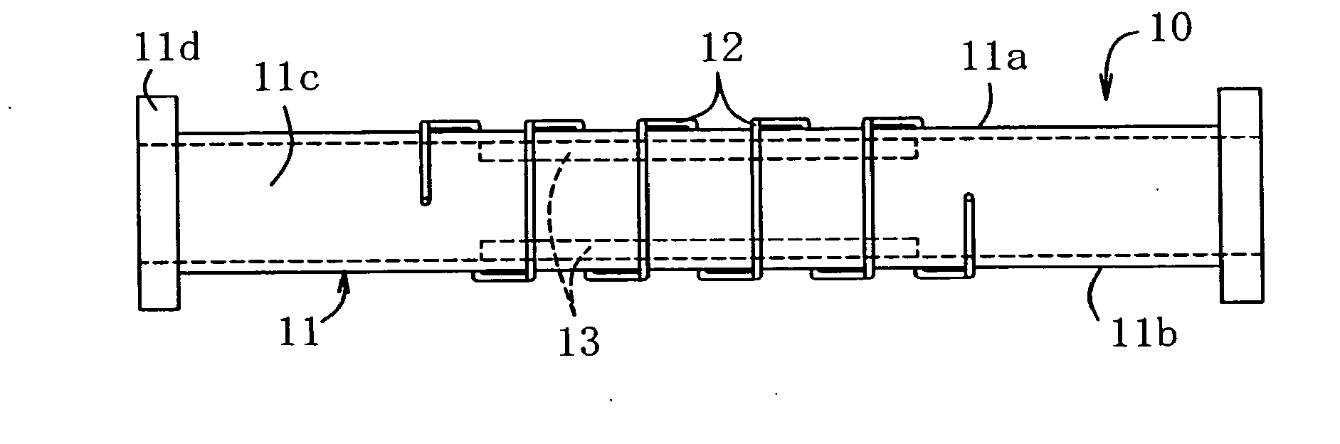
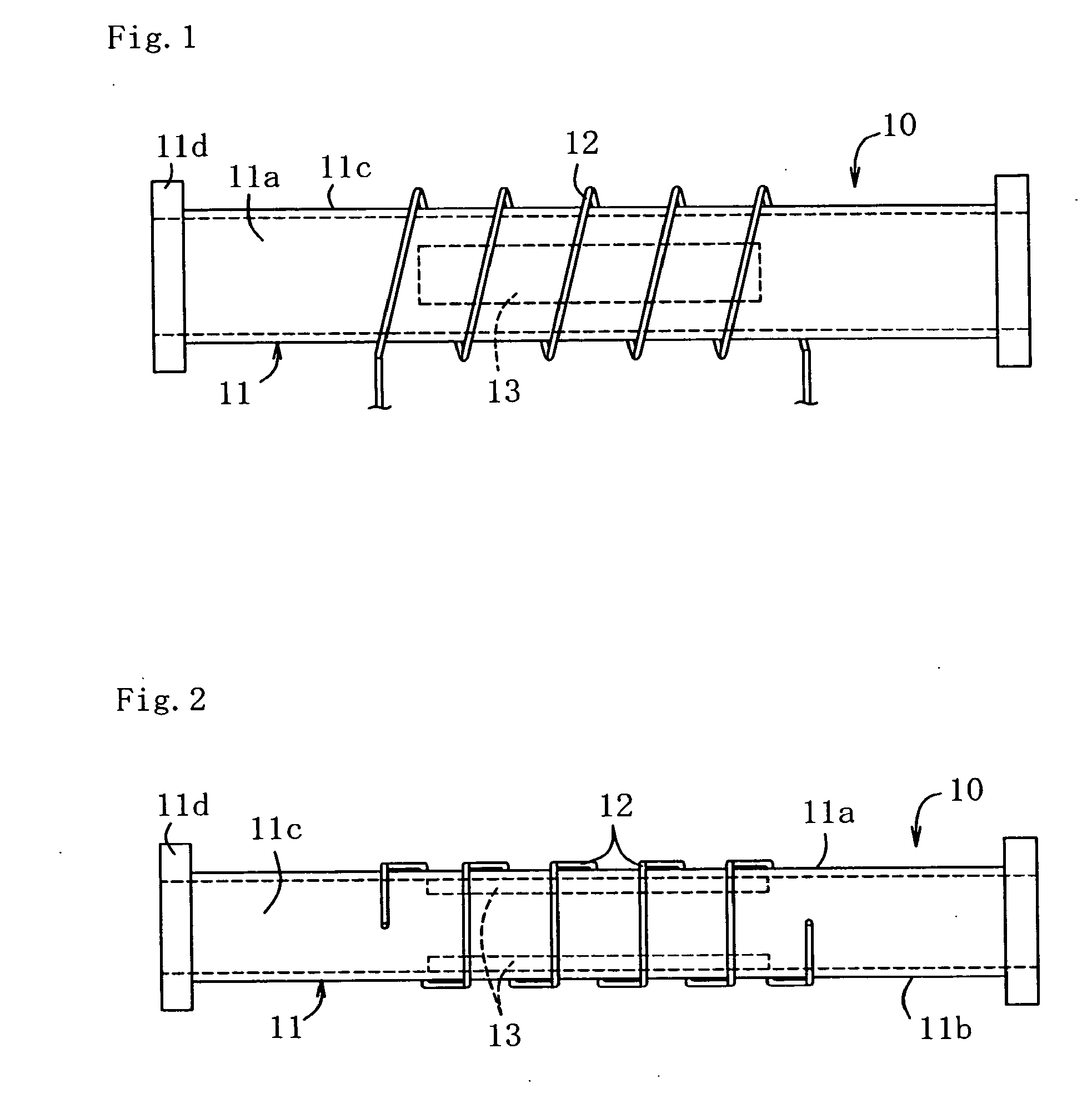
[0053]As shown in FIGS. 1 and 2, a ferrite phase shifter 10 according to a first embodiment of the invention includes a substantially square cylindrical rectangular waveguide 11 formed by a top face 11a, a bottom face 11b and two side faces 11c, and blade-like flanges 11d to serve as coupling sections for coupling with other rectangular waveguides are formed on both longitudinal ends of the waveguide. A coil 12 through which a current is passed is substantially helically wound around the periphery of the rectangular waveguide 11 substantially in the middle thereof. The coil 12 is wound such that it diagonally extends outside the top face 11a and the bottom face 11b and such that it substantially vertically extends on the side faces 11c. The coil 12 is wound in a position substantially corresponding to the position of ferrites 13 which will be described later.

[0054]A rectangular ferrite 13 in the form of an elongate sheet is provided on each...

second embodiment

[Ferrite Phase Shifter of Second Embodiment]

[0060]In a ferrite phase shifter 10 according to a second embodiment of the invention, as shown in FIG. 4, a dielectric layer 14 is provided throughout each of wide surfaces on one side of ferrites 13 (wide surfaces opposite to mounting surfaces of the ferrites) or surfaces of the ferrites 13 facing each other, and the dielectric layers 14 are provided to face each other. Although the dielectric layers 14 of the present embodiment are in the form of sheet-like dielectric bodies secured on the ferrites 13, the dielectric layers 14 may be provided in any appropriate mode. For example, the dielectric layers 14 may be coatings provided on the ferrites 13. The material of the dielectric layers 14 may be appropriately selected from a certain range of usable materials, and it is preferable to use a material resulting in small loss of a high frequency wave and having high heat resistance. For example, alumina ceramic is preferred. The configuratio...

third embodiment

[Ferrite Phase Shifter of Third Embodiment]

[0062]In a ferrite phase shifter 10 according to a third embodiment of the invention, as shown in FIGS. 5 and 6, a coil 12 is wound around a rectangular waveguide 11 in a number of turns smaller than that in the first embodiment. A yoke 15 is provided at each of outer walls of atop face 11 and a bottom face 11b which are wide surfaces of the rectangular waveguide 11, the yoke 15 being provided in a position substantially corresponding to the position of an elongate sheet-like ferrite 13.

[0063]The yokes 15 are formed like sheets which are C-shaped in a side view thereof, and the yokes are disposed so as to enclose the coil 12 from outside with their C-shaped configuration. Both ends of the yokes are positioned in association with both ends of the respective ferrites 13 in the longitudinal direction thereof which agrees with the longitudinal direction of the rectangular waveguide 11. The ends of the yokes are secured to the outer walls of the...


PUM


Abstract

In a ferrite phase shifter, a temperature rise at ferrites can be suppressed to maintain the characteristics of the frites even when used at high power. Thus, the phase shifter can stably demonstrate high performance. The ferrite phase shifter includes a rectangular waveguide, substantially sheet-like ferrites disposed to face each other with respective mounting surfaces kept in tight contact with inner walls of wide surfaces of the rectangular waveguide facing each other, and a coil which is wound around the periphery of the rectangular waveguide in a position substantially corresponding to the position of the ferrites and through which a current is passed.

Description

BACKGROUND OF THE INVENTION[0001]1. Field of the Invention[0002]The present invention relates to a ferrite phase shifter which generates a magnetic field by passing a current through a coil from outside of a rectangular waveguide to change magnetic characteristics of a ferrite and to change a waveguide wavelength of a high frequency wave propagating in the, waveguide, thereby changing the phase of the high frequency wave. The invention also relates to an automatic matching apparatus having such a ferrite phase shifter.[0003]2. Description of the Related Art[0004]Ferrite phase shifters are known, in which a ferrite is disposed in a waveguide to generate a magnetic field for changing the phase of a high frequency wave propagating in the waveguide. For example, such a ferrite phase shifter is configured as shown in FIGS. 18 to 20. A ferrite phase shifter 100 shown in FIGS. 18 to 20 includes a substantially square cylindrical rectangular waveguide 101 formed by a top face 101a, a bottom...

Claims


Application Information

Patent Timeline
Patent Type & Authority Applications(United States)
IPC IPC(8): H01P1/19
CPCH01P1/195H01P1/19H01P1/182
Inventor SHINOHARA, KIBATSUTSURUOKA, SHIGETSUGU
Owner NIPPON KOSHUHAKK
Why Eureka
Try Eureka