Bearing device for wheel

a bearing device and wheel technology, applied in the direction of bearing unit rigid support, coupling, transportation and packaging, etc., can solve the problems of spline fitting, cost increase, tooth surface damage, etc., and achieve high coupling strength, high reliability, and easy and accurate confirmation of the accuracy of the re-formed recess-projection fitting structure.

Active Publication Date: 2012-11-08
NTN CORP
View PDF1 Cites 12 Cited by
  • Summary
  • Abstract
  • Description
  • Claims
  • Application Information

AI Technical Summary

Benefits of technology

[0030]As described hereinabove, according to the first invention of the present application, even when, in particular, the recess-projection fitting structure is re-formed by re-coupling the hub wheel and the outer joint member to each other, accuracy of the re-formed recess-projection fitting structure can be easily and accurately confirmed. With this, it is possible to provide the highly reliable bearing device for wheel which maintains high coupling strength and excellent torque transmission performance even after repair.
[0031]Further, according to the second invention of the present application, the hub wheel and the outer joint member can be coupled and re-coupled to each other with high accuracy even after being separated from each other. Still further, the hub wheel and the outer joint member can be easily separated from and re-coupled to each other. Thus, a bearing part and a joint part can be separated and individually undergo inspection, maintenance, repair, and the like. As a result, high maintenance properties can be assured. In addition, also when the hub wheel and the outer joint member are re-coupled to each other, high coupling accuracy can be achieved. Thus, high assembly accuracy of the bearing device for wheel can be maintained even through repeated inspection, maintenance, repair, and the like.

Problems solved by technology

However, coupling of the hub wheel and the outer joint member to each other by spline fitting has problems as follows.
First, it is necessary for both the shaft portion of the outer joint member and the hub wheel to be provided with a spline, which leads to a cost increase.
Further, regarding fitting of recesses and projections of the male spline and the female spline to each other, which is necessary to perform at the time of press-fitting, when press-fitting is performed by tooth surface fitting, tooth surfaces may be damaged, for example, by being scraped.
Meanwhile, when press-fitting is performed by large diameter fitting, backlash in the circumferential direction is liable to occur.
The backlash in the circumferential direction may lead to deterioration in torque transmission efficiency and generation of abnormal noise.
Further, for example, when the bearing device for wheel is repaired, it may be difficult to repair the bearing device for wheel under a state in which the hub wheel and the outer joint member are coupled to each other.

Method used


Image

  • Bearing device for wheel
  • Bearing device for wheel
  • Bearing device for wheel

Examples


first embodiment

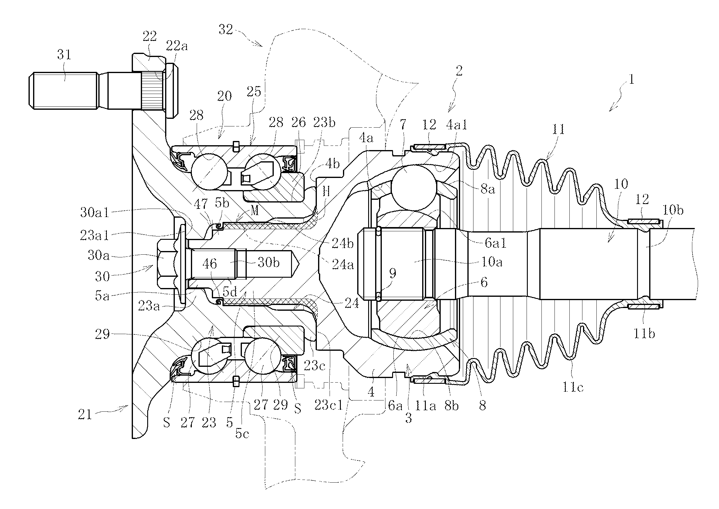
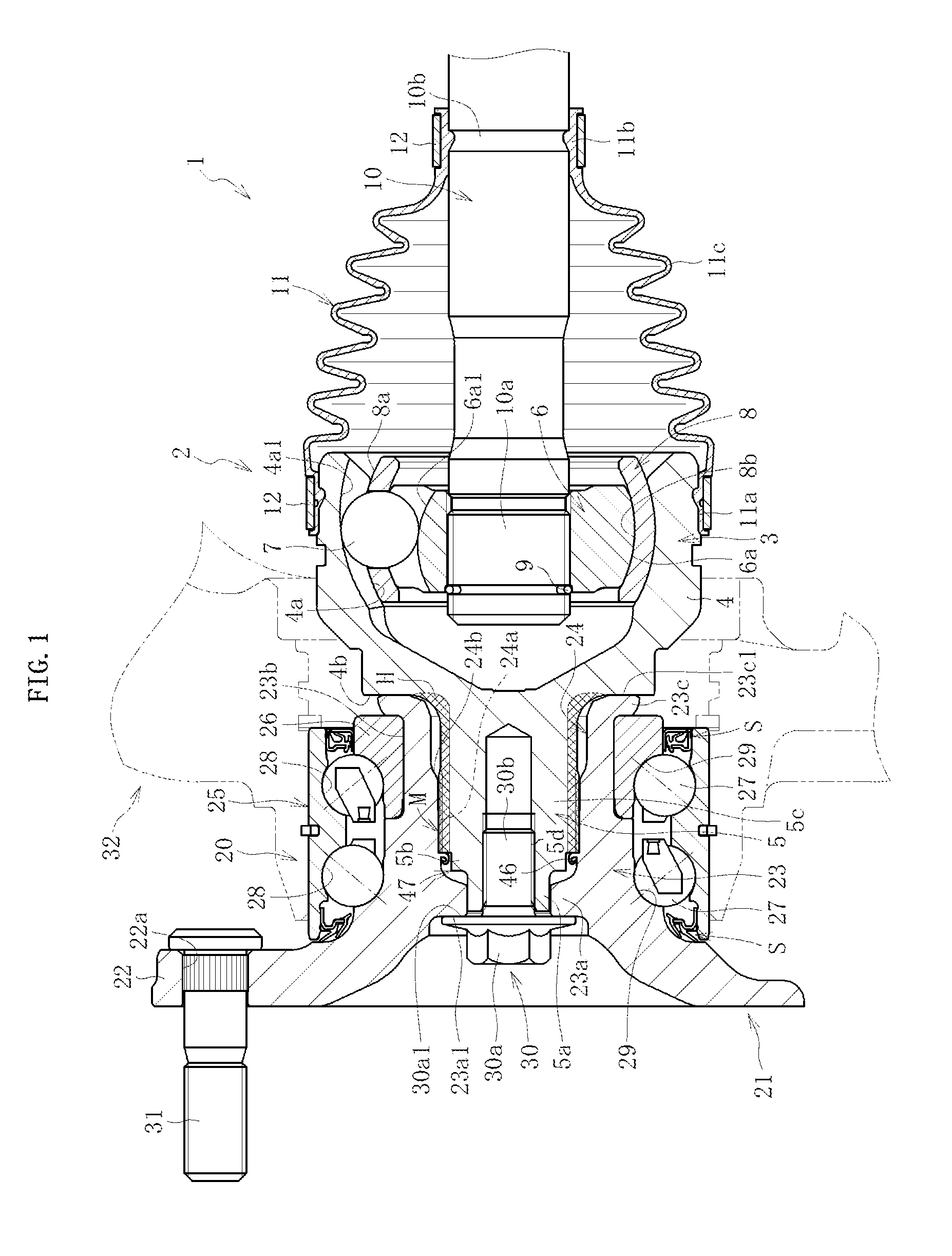
[0082]FIG. 1 is a sectional view of a bearing device for wheel 1 according to the first invention of the present application. A main part of the bearing device for wheel 1 illustrated in FIG. 1 is formed of an integral piece of a double row bearing for wheel 20, which comprises a hub wheel 21, and a constant velocity universal joint 2. Note that, in the following description, an inboard side and an outboard side respectively refer to sides on an inner side and an outer diameter side in a vehicle width direction of a vehicle under a state in which the bearing device for wheel 1 is mounted to the vehicle. In FIG. 1, the right side corresponds to the inboard side and the left side corresponds to the outboard side.

[0083]A main part of the constant velocity universal joint 2 is formed of an outer joint member 3, an inner joint member 6 arranged on an inner diameter side with respect to the outer joint member 3, a plurality of balls 7 interposed between the outer joint member 3 and the in...

second embodiment

[0136]FIG. 10 is a sectional view of a bearing device for wheel 1 according to the first invention of the present application. The bearing device for wheel 1 illustrated in FIG. 10 is different from the bearing device for wheel 1 illustrated in FIG. 1 mainly in that the end surface 23c1 of the crimped portion 23c of the hub wheel 21 and the back surface 4b of the mouth portion 4 are kept out of contact with each other. In this case, as illustrated also in FIG. 11A on an enlarged scale, a gap 60 is provided between the end surface 23c1 of the crimped portion 23c and the back surface 4b of the mouth portion 4. The gap 60 thus formed more effectively prevents generation of abnormal noise which may be caused by contact of the mouth portion 4 of the outer joint member 3 and the hub wheel 21.

[0137]In this way, when the end surface 23c1 of the hub wheel 21 and the back surface 4b of the mouth portion 4 are kept out of contact with each other, foreign matter intrusion prevention means for t...

third embodiment

[0217]FIG. 28 is a sectional view of a bearing device for wheel according to the second invention of the present application. The bearing device for wheel illustrated in FIG. 28 is different from that illustrated in FIG. 16 mainly in that a step portion 122f is provided at an outboard-side end portion of the cylindrical portion 120 of the hub wheel 101 and that a ring-like receiving member 160 separate from the hub wheel 101 is fitted to the step portion 122f so that the head portion 150a of the bolt member 150 is received by the receiving member 160. Specifically, in this embodiment, an outboard-side end surface 160a of the receiving member 160 serves as a receiving surface F′ for receiving the seat surface 150a1 of the bolt member 150. Other components are substantially the same as those of the bearing device for wheel illustrated in FIG. 16. Thus, the same reference symbols are used to omit redundant description.

[0218]Note that, although not described with reference to the drawin...


PUM


Abstract

A hub wheel (21) and an outer joint member (3) are coupled to each other through intermediation of a recess-projection fitting structure (M). The recess-projection fitting structure (M) can be separated by being applied with a pulling-out force in an axial direction under a state in which a bolt member (30) is removed, and can be re-formed by re-screwing the bolt member (30) into a bolt hole (5d). The hub wheel (21) comprises a receiving portion (23a) for receiving the bolt member (30). The shaft portion (5) has a small diameter portion (5a) serving as a fit-in portion to be fitted along an inner periphery of the receiving portion (23a) under a state in which the recess-projection fitting structure (M) is formed. The small diameter portion (5a) is used as a part for confirming the accuracy and the state of the recess-projection fitting structure (M).

Description

TECHNICAL FIELD[0001]The present invention relates to a bearing device for wheel, for supporting a wheel of a vehicle such as an automobile so that the wheel is freely rotatable with respect to a vehicle body.BACKGROUND ART[0002]As a bearing device for wheel, there have been developed the following types: a structure called a first generation type in which roller bearings are used in double row combination; a second generation type evolved from the first generation type, in which a vehicle body mounting flange is integrated with an outer member; a third generation type in which one of two inner raceway surfaces of the double row roller bearing is formed on an outer periphery of a hub wheel provided with a wheel mounting flange; and a fourth generation type in which the one of the two inner raceway surfaces of the double row roller bearing is formed on the outer periphery of the hub wheel, and another of the two inner raceway surfaces of the double row roller bearing is formed on an ...

Claims


Application Information

Patent Timeline
Patent Type & Authority Applications(United States)
IPC IPC(8): F16C13/02
CPCF16D3/223F16C33/586F16D2003/22326B60B27/0005B60B27/0026B60B27/0042B60B27/0084B60B27/0094F16C19/186F16C35/0635F16D1/072F16D1/0858B60Y2200/11F16C2326/02F16D2001/103
Inventor UMEKIDA, MITSURUTOMOGAMI, SHINSHIBATA, KIYOTAKEASANO, YUICHIKURA, HISAAKI
Owner NTN CORP
Why Eureka
Try Eureka