

Electrode dryer and method for drying electrode
a technology of electrode dryer and electrode sheet, which is applied in the direction of dryer with progressive movement, cell components, lighting and heating apparatus, etc. it can solve the problems of uneven coating of electrode sheet, etc., and achieve the effect of reducing uneven coating and stable production of electrodes
- Summary
- Abstract
- Description
- Claims
- Application Information
AI Technical Summary
Benefits of technology
Problems solved by technology
Method used
Image

Examples
embodiment 1
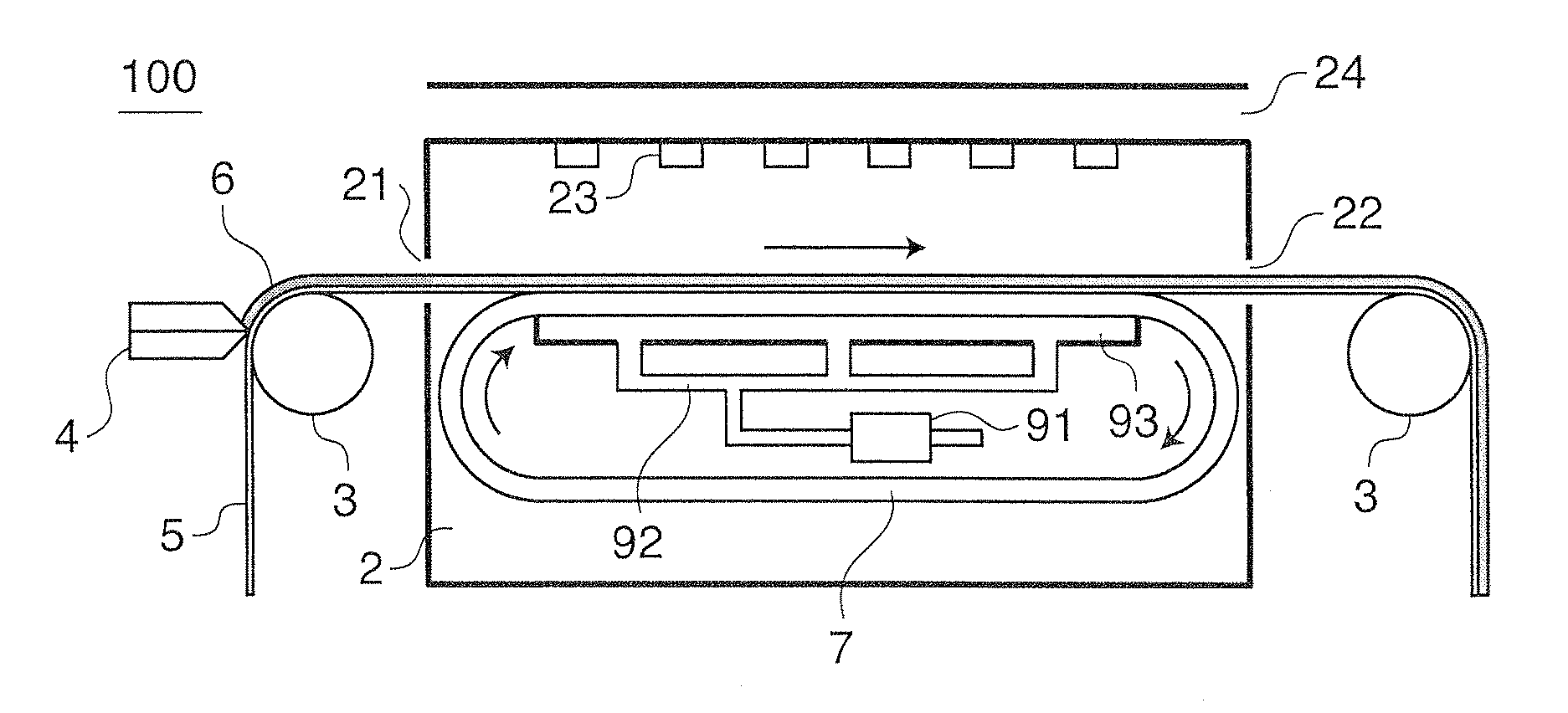
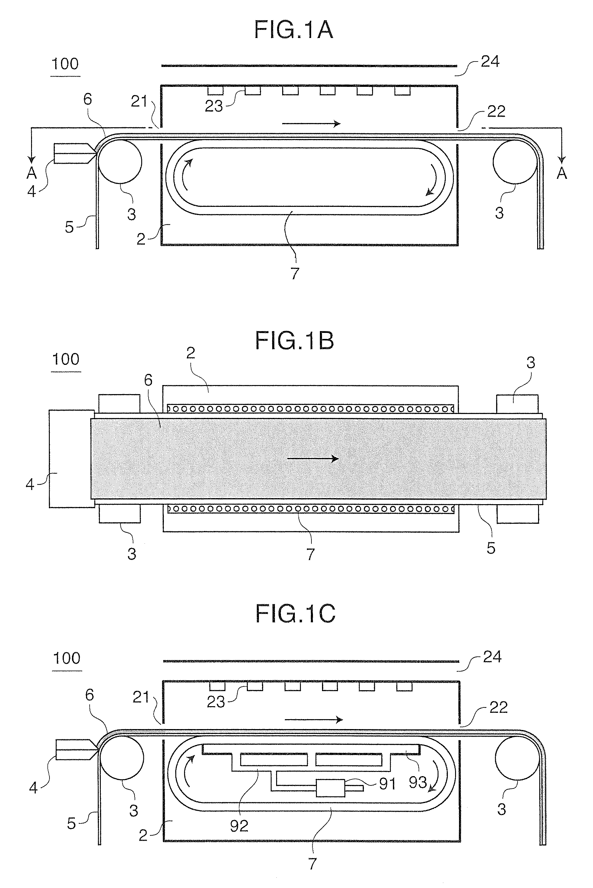
[0032]FIGS. 1A and 1B are schematic configuration diagrams of an electrode dryer 100 according to Embodiment 1. Specifically, FIG. 1A is a side view of the electrode dryer 100, and FIG. 1B is a view taken along a line A-A in FIG. 1A. The electrode dryer 100 mainly includes a drying furnace 2, support rollers 3, a coater 4 and a mounting member 7. The electrode dryer 100 is an apparatus that dries a band-like electrode base material 5 coated with an electrode slurry 6 as a coating material by the coater 4 while conveying the electrode base material 5.
[0033]The drying furnace 2 is in a box shape having openings at predetermined positions in opposite sides. The electrode base material 5 coated with the electrode slurry 6 on one surface is introduced to the drying furnace 2 through an entrance 21 provided in one side of the drying furnace 2 (left side in FIG. 1A), goes through a predetermined drying process in the drying furnace 2, and then conveyed out of the drying furnace 2 through a...
embodiment 2
[0050]Next, Embodiment 2 will be described. Embodiment 2 has the same general configuration as Embodiment 1 except for the shape of the mounting member.
[0051]FIG. 3 is a schematic configuration diagram of an electrode dryer 200 according to Embodiment 2 seen from a side. A mounting member 8 is composed of a plurality of metallic rollers 81 arranged planarly with their rotation axes oriented in the same direction, for example. The number of the metallic rollers 81 can be determined appropriately according to the conditions of the electrode base material 5 being conveyed.
[0052]FIG. 4 is a diagram illustrating a shape of each metallic roller 81. The radius r of the metallic rollers 81 can be determined in view of the fact that a too large radius results in a large gap between the electrode base material 5 and the metallic rollers 81 connected in series to fail in stable holding of the electrode base material 5, though it depends on the conditions of the electrode base material 5 being ...
embodiment 3
[0055]Next, Embodiment 3 will be described. Embodiment 3 has the same general configuration as Embodiment 1 and Embodiment 2 except for the shape of the mounting member.
[0056]FIG. 5 is a schematic configuration diagram of an electrode dryer 300 according to Embodiment 3 seen from a side. A mounting member 9 is made of a metallic plate, for example. Preferably, the plate has a plane surface and a width equal to or larger than the width of the electrode base material 5 in a direction perpendicular to the conveyance direction of the electrode base material 5. Since the plane having a width equal to or larger than the width of the electrode base material 5 allows stable holding of the electrode base material 5, the electrode base material 5 is prevented from hanging down or swinging due to hot air during the drying and from having uneven coating as a result. The mounting member 9 may also have the above-described suction mechanism.
[0057]As described above, the electrode base material 5 ...
PUM
| Property | Measurement | Unit |
|---|---|---|
| Width | aaaaa | aaaaa |
Abstract
Description
Claims
Application Information