Liquid crystal light valve structure

A liquid crystal light valve and polarizer technology, applied in optics, nonlinear optics, instruments, etc., can solve the problems of diffusion and angle dependence variation, affecting product diffusion and angle dependence, uneven glue coating, etc. Achieve the effects of reducing uneven coating of glue, improving transmittance and improving performance level

Active Publication Date: 2015-06-17
TRULY SEMICON
View PDF3 Cites 0 Cited by
  • Summary
  • Abstract
  • Description
  • Claims
  • Application Information

AI Technical Summary

Problems solved by technology

As previously mentioned, the diffuse and angular dependence of light transmittance τ V There is a relationship, which makes the diffusion and angle dependence of existing welding mask products worse
In addition, when there are many polarizers, it is easy to have the problem of uneven glue coating, which will also affect the diffusion and angle dependence of the product

Method used


Image

  • Liquid crystal light valve structure
  • Liquid crystal light valve structure
  • Liquid crystal light valve structure

Examples


Embodiment 1

[0086] Such as Figure 7a ~ Figure 7d As shown, the glued structure is fully coated with glue. From top to bottom are filter 1, glue 2-1, polarizer 3-1, LCD4-1, glue 2-2, polarizer 3-2, LCD4-2, polarizer 3-3, glue 2- 3. Protective sheet5. This embodiment adopts the full coating method of glue, the difference between the selected glue material (transmittance, refractive index, viscosity, etc.) and gluing process parameters and gluing equipment, etc., has a great influence on the diffusion and angle dependence; in addition , the coating is easy to cause uneven thickness of the coating layer, or the glue is not vacuum-treated or the vacuum treatment is not thorough, or there are too many dust particles in the coating environment, which will cause air bubbles or foreign matter residues after the glue is coated. The angle dependence has an influence; so it is necessary to choose a very suitable glue material to match the performance parameters of the structure of two LCDs and thr...

Embodiment 2

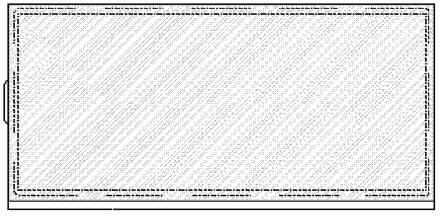
[0089] Such as Figure 8a ~ Figure 8e As shown, the glued structure is coated with glue all around. From top to bottom, they are filter 1, polarizer 3-1, LCD 4-1, polarizer 3-2, LCD 4-2, polarizer 3-3, and protective sheet 5. Glue them around together.

[0090] Figure 8d ~ Figure 8e It is not very intuitive to see whether the polarizer 3-2 is pasted on the bottom of the LCD 4-1 or on the top of the LCD 4-2. In fact, it can be pasted on any LCD.

[0091] In this embodiment, the glue used not only satisfies the bonding of LCD4-1 and LCD4-2, but also satisfies reliability conditions, and has no effect on diffusion and angle dependence.

Embodiment 3

[0093] Such as Figure 9a ~ Figure 9d As shown, the structure is glued with double-sided adhesive tape. From top to bottom are filter 1, shading tape 6-1, polarizer 3-1, LCD4-1, shading tape 6-2, polarizer 3-2, LCD4-2, polarizer 3-3, shading Adhesive tape 6-3, protective sheet 5.

[0094] Figure 9c ~ Figure 9d It only indicates that the polarizer 3-2 is pasted on the LCD4-2, and the light-shielding tape 6-2 is between the LCD4-1 and the polarizer 3-2; similarly, the polarizer 3-2 can be pasted on the bottom of the LCD4-1 , the shading tape 6-2 is in the middle of the LCD4-2 and the polarizer 3-2.

[0095] In this embodiment, the double-sided adhesive tape (black light-shielding tape or ordinary double-sided adhesive tape or others) is bonded up and down. It is also possible to use double-sided tape (black shading tape or ordinary double-sided tape or other) to glue the surrounding parts of the area (not shown in the picture), but it is necessary to control the position of...


PUM

PropertyMeasurementUnit
pore sizeaaaaaaaaaa
pore sizeaaaaaaaaaa

Abstract

The invention discloses a liquid crystal light valve structure which comprises at least two LCDs (liquid crystal display), wherein an optical filter is arranged at the outer side of the top LCD; a protective plate is arranged at the outer side of the bottom LCD, and a polaroid is arranged between the adjacent LCDs, between the top LCD and the light filter sheet and between the bottom LCD and the protective plate respectively. According to the liquid crystal light valve structure, the transmittance of the light is benefit to be improved by reducing the polaroid; uneven glue coating phenomenon is reduced, and the performance level of diffusion and angle dependence of a mask product for electric soldering is improved.

Description

technical field [0001] The present invention relates to a device or device for controlling the intensity, color, phase, polarization or direction of light from an independent light source, in particular a liquid crystal light valve structure. Background technique [0002] Welding arc light mainly includes infrared rays, visible light rays and ultraviolet rays. This kind of arc light is very harmful to human eyes and can even cause blindness. The liquid crystal light valve is a liquid crystal TN product applied on the electric welding mask, which can protect the eyes. This is because the liquid crystal light valve can double filter light, which can block all the strong light of the welding arc from passing through during electric welding operations, convert the strong arc light into soft light, and avoid the harmful ultraviolet and infrared radiation generated by the arc and the damage caused by the strong welding light to the eyes. Injury, put an end to the occurrence of el...

Claims


Application Information

Patent Timeline
Patent Type & Authority Patents(China)
IPC IPC(8): G02F1/1347G02F1/1335G02F1/13G02F1/13363
Inventor 王海涛徐响战李明毅
Owner TRULY SEMICON
Why Eureka
Try Eureka