Reciprocal enhancement of reverse osmosis and forward osmosis

Active Publication Date: 2012-11-15
I D E PROJECTS LTD
View PDF6 Cites 38 Cited by
  • Summary
  • Abstract
  • Description
  • Claims
  • Application Information

AI Technical Summary

Problems solved by technology

However, this method is characterized by the following disadvantages: (1) Water treatment—Both the river and ocean water have to be intensively cleaned to remove all suspended solids.
Those types of CP limit FO flux and efficiency of the process to such extend that making it not cost effective.
Compared with pressure-driven RO membrane processes, the FO process exhibits unparalleled advantages of nearly no hydraulic pressure operation, nearly complete rejection of many contaminants, and potentially low me

Method used


Image

  • Reciprocal enhancement of reverse osmosis and forward osmosis
  • Reciprocal enhancement of reverse osmosis and forward osmosis
  • Reciprocal enhancement of reverse osmosis and forward osmosis

Examples


example 1

[0048]The following example (illustrated in FIG. 2B) is presented for the following values of pressures and mass balance of flow entering and exiting membrane element 110 (the FO drawing side of membrane 115 which receives the brine is denoted by 117, the FO feed side is denoted by 118): Bfi—Flow brine in (e.g. 1 m3 / sec), Bfo—Flow brine out (e.g. 1.9 m3 / sec), WWi—Flow waste water in (e.g. 1 m3 / sec), WWo—Flow waste water out (e.g. 0.1 m3 / sec), PObi—Osmotic pressure brine in (e.g. 60 bar), PObo—Osmotic pressure brine out (e.g. 30 bar), POwi—Osmotic pressure waste water in (e.g. 0.3 bar), POwo—Osmotic pressure waste water out (e.g. 0.6 bar), PGbi—Gauge pressure brine in (e.g. 60 bar), PGbo—Gauge pressure brine out (e.g. 59.9 bar), PGwi—Gauge pressure waste water in (e.g. 33 bar), PGwo—Gauge pressure waste water out (e.g. 32 bar), the net driving pressure (NDF) that provide penetration of waste water into the stream of brine is calculated as follows: PGb-PGw-POb+POw=59.5−32.4−31.6+0.45=...

example 2

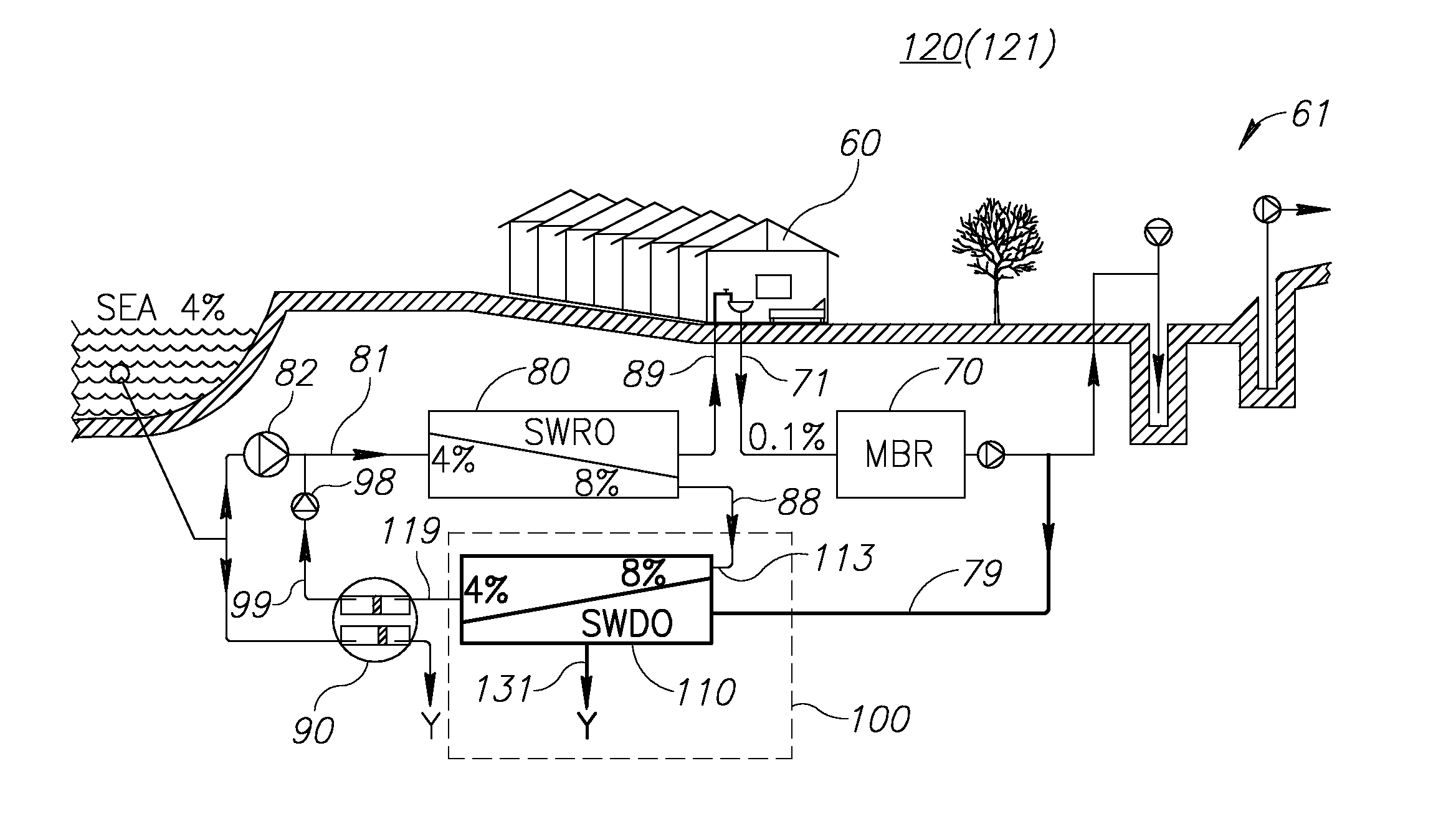
[0059]The process is exemplified using Pressure Retarded Osmosis (PRO) as one of many FO applications. FIG. 3A illustrates the desalination system at a FO state (121) of recovering osmotic pressure of the brine generated by RO unit 80, FIG. 3B illustrates the pressures on membrane 115 (as rejection layer) in this state (121), with the CP that is built (across membrane 115, in volume 127 as external CP and in volume 128 as internal CP, e.g. in support layer 116) by the end of the FO stage. FIG. 4A illustrates the desalination system at a RO, or washing state (122) of removing the CP in order to rehabilitate the osmotic gradient across membrane 115, such as to efficiently re-apply the FO process. FIG. 4B illustrates the pressures on membrane 115 in this state (122), without the CP, anticipating the inception of the next FO stage. Table 2 summarizes the pressures at the beginning of the FO stage (121), at the end of the FO stage (121), and at the beginning of the flushing phase (122). ...


PUM

PropertyMeasurementUnit
Pressureaaaaaaaaaa
Salinityaaaaaaaaaa
Concentrationaaaaaaaaaa

Abstract

Periodically operating a forward osmosis (FO) semi-permeable membrane element in reverse osmosis (RO), to yield product extraction on a feed side of the membrane, to flush out a concentration polarization (salt concentration of the feed side and dilution of draw solution on the draw side) across the membrane. Utilizing treated waste water to generate the flushing solution of low osmotic pressure, and gauge pressurizing the flushing solution to the gauge pressure of the draw solution to keep a constant gauge pressure of the solutions. FO process is interrupted every 5-20 minutes for a 10-60 seconds long flushing RO process, thereby increasing the FO throughput five fold and recovering power from the increased throughput, i.e. from the osmotic pressure of the brine.

Description

CROSS REFERENCE TO RELATED APPLICATIONS[0001]This application claims the benefit of U.S. Provisional Patent Applications No. 61 / 358,969 filed on Jun. 28, 2010, and U.S. Provisional Patent Applications No. 61 / 264,256 filed on Nov. 25, 2009, which are incorporated herein by reference.BACKGROUND[0002]1. Technical Field[0003]The present invention relates to the field of desalination, and more particularly, to recovery of osmotic power.[0004]2. Discussion of Related Art[0005]In reverse osmosis (RO) desalination, water is extracted through a membrane from a pressurized feed, generating pressurized brine. The brine is both gauge pressurized (mechanical pressure) and osmotic pressurized (having a high salt concentration. Efforts have been to conducted to use the pressure of the brine to pressurize the feed, thereby recovering some of the high energy costs involved in pressurizing the feed.[0006]Work or pressure exchangers (e.g. DWEER, ERI) are basically reciprocal pumping devices that are f...

Claims


Application Information

Patent Timeline
IPC IPC(8): B01D61/06B01D61/08B01D65/08
CPCB01D61/002B01D61/06B01D65/08B01D2321/04B01D2321/2083B01D2321/06C02F1/445C02F3/1268C02F2103/08C02F2209/44C02F1/441Y02W10/30Y02A20/131Y02W10/10
Inventor LIBERMAN, BORIS
Owner I D E PROJECTS LTD
Why Eureka
Try Eureka