Flame Sense Circuit for Gas Pilot Control

a pilot control and flame sense technology, applied in the direction of lighting and heating apparatus, combustion process, combustion regulation, etc., can solve the problems of weak flame current, marginal flame, poor quality, etc., and achieve the effect of reducing the risk of fire, and reducing the safety of pilot control

Inactive Publication Date: 2012-11-15
INT CONTROLS & MEASUREMENT
View PDF5 Cites 32 Cited by
  • Summary
  • Abstract
  • Description
  • Claims
  • Application Information

AI Technical Summary

Benefits of technology

[0009]Accordingly, it is an object of the present invention to provide a flame rectification flame-sense circuit that overcomes the above-mentioned drawback(s) of t

Problems solved by technology

A voltage that is within one given voltage range or another can mean the presence of flame at the pilot gas burner, or can also mean that the flame is of marginal, poor, or good quality.
A voltage that is outside that range, i.e., above it at a first or second high voltage level, can mean that flame is absent or that there is an electrical problem with the flame rod.
Up until now, these arrangements could only detect the presence or absence of flame, but have not been able to quantify or evaluate the condition of flame when it is present, even though that information would be useful during control installation or for troubleshooting.
Examples of flame quality issues that would be useful, if they could be distinguished and detected, include a coated or con

Method used


Image

  • Flame Sense Circuit for Gas Pilot Control
  • Flame Sense Circuit for Gas Pilot Control

Examples


Embodiment Construction

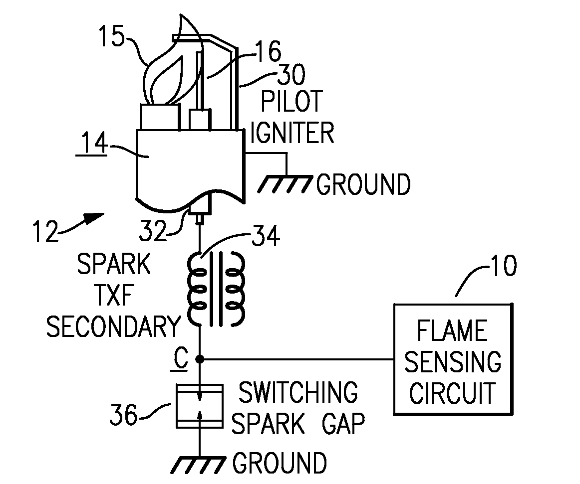
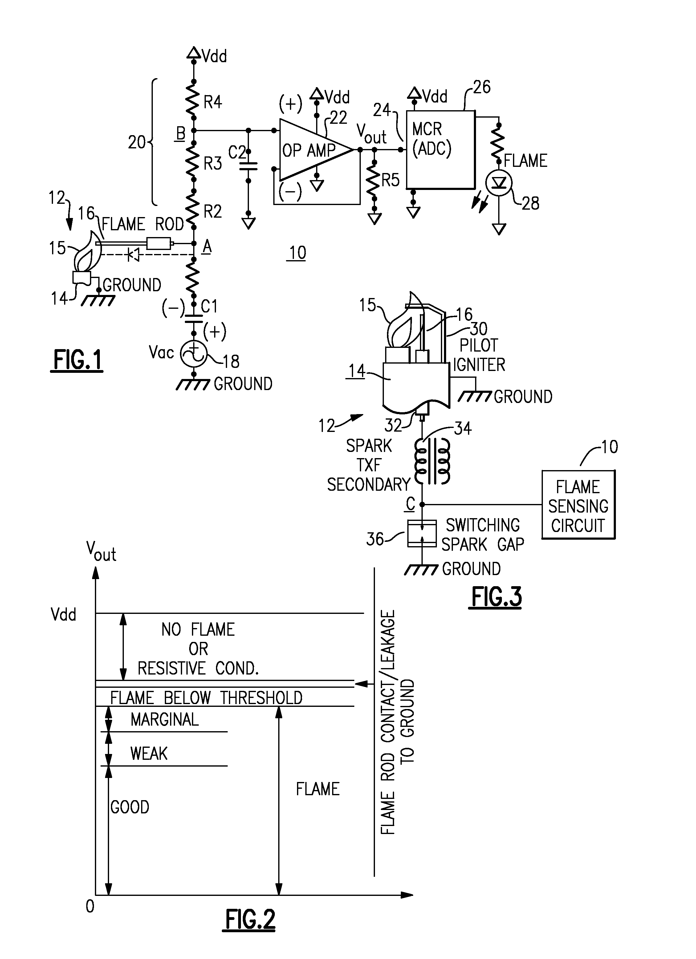
[0022]With reference now to the Drawing, FIG. 1 shows a general arrangement of a flame sense circuit 10, for monitoring the quality of flame of a gas burner pilot 12. The pilot 12 has a chassis 14, which is electrically grounded with a flame 15, when present, extending upward, and with a flame rod 16, which is electrically isolated, extending into the envelope of the flame 15.

[0023]In the flame sense circuit 10, there is an AC voltage source 18, e.g., 12-volt or 24-volt AC 60 Hz thermostat power, coupled between a ground point and one terminal of a capacitor C1. The other terminal of the capacitor C1 is coupled to a junction point or node A, which is in turn connected to the flame rod 16. Favorably, this capacitor has a capacitance value of about 2.2 nanofarads, and there may be a protective resistor R1 between the capacitor C1 and the flame rod 16 to limit current in the event that the flame rod touches the chassis and grounds. The resistor R1 favorably has a resistance value of ab...


PUM


Abstract

A flame sense circuit for a gas burner control employs a flame rod for flame rectification. An AC source applies an AC wave through a capacitor to the flame rod, and the flame rod is also connected via a resistive voltage divider to a DC voltage source. A voltage divider node is connected to a voltage follower, which impedance-matches an ADC input of a microprocessor controller. The flame sense circuit senses conditions of no-flame, and flame rod in contact with or leaking to ground, and when flame is present can quantify sensed flame as good, weak and marginal.

Description

BACKGROUND OF THE INVENTION[0001]This present invention relates to control devices for controlling gas fired appliances, such as furnaces and water heaters, and is more particularly concerned with a flame-sense arrangement that operates according to the principle of flame rectification.[0002]The present invention is also concerned with a gas appliance control that employs an intermittent ignition system for the pilot light flame of the appliance in which the igniter or spark feature can also serve as a flame rod of the flame-sensor arrangement.[0003]Flame rectification refers to a method of flame detection, using the property of a flame in which a plasma or ionized region within the flame serves as a unidirectional conductor, so that a current can flow from an interior of the flame towards the outside of the flame. Typically, a flame rod or conductive probe penetrates the flame envelope, and serves as anode, while a grounded pilot gas jet on the burner chassis serves as cathode. The...

Claims


Application Information

Patent Timeline
IPC IPC(8): F23N5/12
CPCF23N2029/12F23N5/123F23N2229/12
Inventor RACAJ, BASHKIM
Owner INT CONTROLS & MEASUREMENT
Why Eureka
Try Eureka