Dental implant

a technology for dental implants and implants, applied in dentistry, dental surgery, medical science, etc., can solve the problems of increased bruxism, inability to adequately absorb masticatory stress on the artificial tooth structure, and all these materials have the disadvantage of being too stiff and brittle, and achieves convenient application and positioning, cost-effective, and advantageous fixation of the abutment on the implant.

Active Publication Date: 2012-11-15
NORDIN PETER +1
View PDF35 Cites 15 Cited by
  • Summary
  • Abstract
  • Description
  • Claims
  • Application Information

AI Technical Summary

Benefits of technology

[0031]With respect to a separate abutment that is applied on the filling member of the implant, the contact surface of the abutment is preferably constituted by a substantially flat bottom surface at the apical end of the body portion of the abutment. This allows an easy application and positioning of the abutment on the dental implant before its actual fixation. Various fixation methods of the abutment on the implant are conceivable, in particular cementing, screwing or clipping or a combination thereof. Fixation by screwing can be achieved by means of an inward thread or an outward thread in or on the abutment. A particularly advantageous fixation of the abutment on the implant can be achieved in that a receiving bore is provided at the contact surface for receiving a connector portion of the dental implant. Alternatively, a connector portion can be provided at the contact surface configured for insertion into a receiving bore an the dental implant. In particular the cross section of the receiving bore may exhibit a circular, squared, triangular, hexagonal or octogonal shape. In this way, a cost efficient and yet easy applicable and reliable fixation can be realized.
[0032]According to a preferred implementation of the filling member, the optical properties of the fiber-reinforced resin structure are exploited for an advantageous light conduction through the filling member, which can be applied to achieve a proper polymerization of a setting product, such as composite resin cement. Advantageously, the ordered ar

Problems solved by technology

Despite this benefit, all these materials have the disadvantage of being too stiff and brittle as compared to the dentine and cementum of a natural tooth they are supposed to replace and mimic.
In consequence, the masticatory stresses exerted on the artificial tooth structure cannot be adequately absorbed.
This leads to a number of undesirable side effects including an unnatural feeling of pressure while chewing, increased bruxism, and an increased risk of breakage of th

Method used


Image

  • Dental implant
  • Dental implant
  • Dental implant

Examples


Embodiment Construction

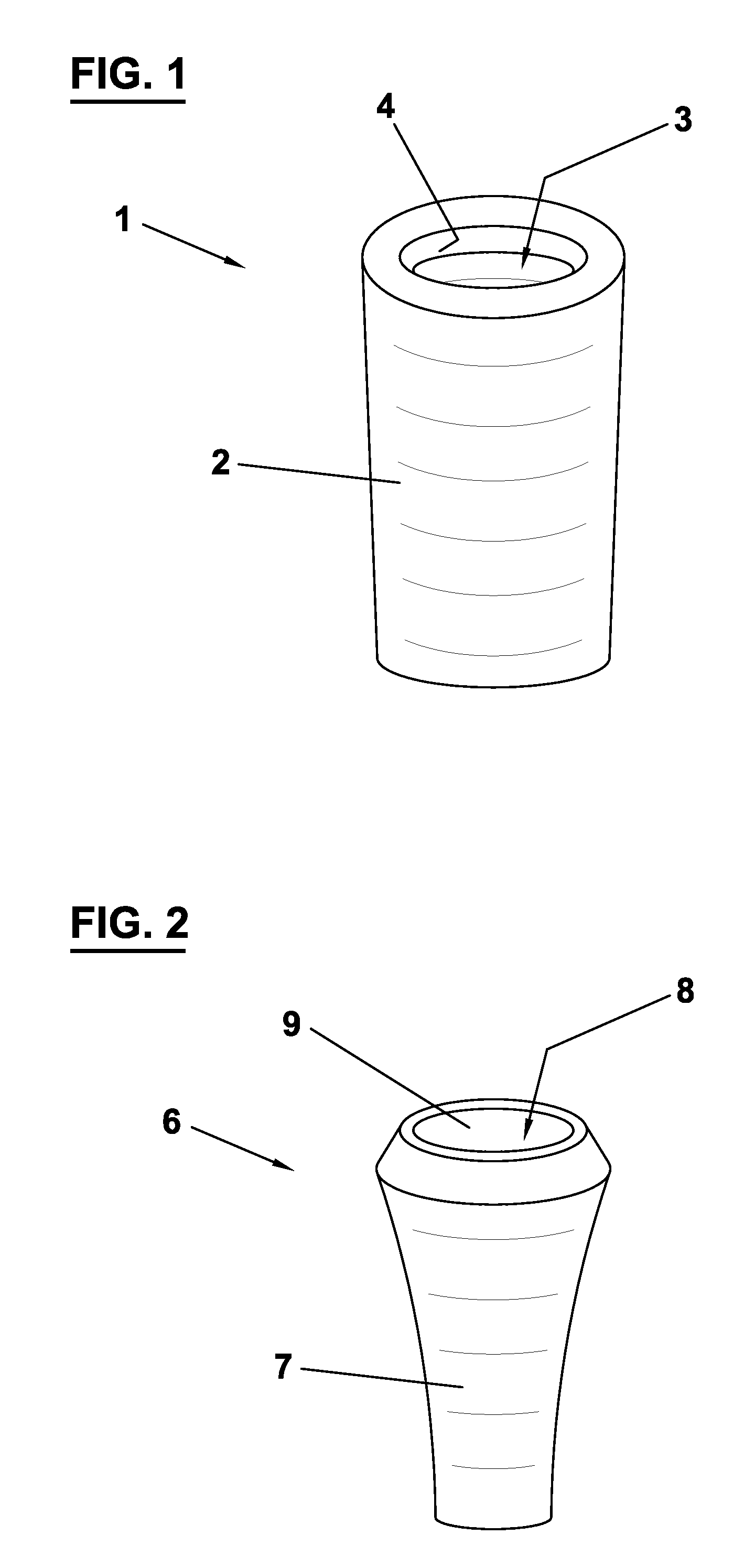
[0038]FIG. 1 depicts an anchoring member 1 constituting a first component of a dental implant. The anchoring member 1 is configured to be anchored into a jawbone and comprises an anchoring wall 2 consisting of titanium, stainless steel, ceramics or another osseointegratable material. The anchoring wall 2 encloses an anchoring cavity 3 extending in an apical direction, wherein the cross section of the cavity 3 continuously decreases in the apical direction. The anchoring member 1 comprises a coronal opening 4 in which other constituents of the implant are insertable. The anchoring wall 2 can have an essentially smooth outer surface or it can be provided with retention structures to improve the anchoring in the bone tissue. The thickness of the anchoring wall increases in the apical direction.

[0039]FIG. 2 depicts a sleeve member 6 constituting a second component of the dental implant. The sleeve member 2 is insertable and removable into the anchoring cavity 3 of anchoring member 1 via...


PUM


Abstract

The invention relates to a dental implant configured to be anchored in a jawbone for supporting a dental prosthesis.
In order to allow an adjustment of the tooth restoration structure to properties of a natural tooth the dental implant comprises a jacket member consisting at least in part of an osseo-integratable material and enclosing a cavity in an apical direction, and a filling member consisting of fiber reinforced material and being shaped so as to substantially fill out said cavity.

Description

FIELD OF THE INVENTION[0001]The invention relates to a dental implant configured to be anchored in a jawbone for supporting a dental prosthesis.BACKGROUND OF THE INVENTION[0002]Prosthodontic restorations replacing a natural tooth in a patient's dentition are commonly fixed on a dental implant that is surgically implanted into the patient's jawbone. Typically, since the early work of Per-Ingvar Brånemark of Sweden in 1952, such an implant consists of a titanium screw which resembles a tooth root and comprises a roughened or smooth surface. The majority of dental implants are made out of pure titanium, which is commercially available in four grades depending upon the amount of contained carbon and iron.[0003]An abutment is usually anchored at the coronal end of the dental implant. A dental prosthesis, such as a crown, a fixed bridge retainer or a removable denture, can be attached on the abutment serving as an interface between the dental prosthesis and the dental implant. The abutmen...

Claims


Application Information

Patent Timeline
IPC IPC(8): A61C8/00
CPCA61C8/005A61C8/0086A61C8/0069A61C8/0063
Inventor NORDIN, PETERNORDIN, HARALD
Owner NORDIN PETER
Why Eureka
Try Eureka