Barrier films and high throughput manufacturing processes for photovoltaic devices
What is Al technical title?
Al technical title is built by PatSnap Al team. It summarizes the technical point description of the patent document.
a photovoltaic device and barrier film technology, applied in the field of photovoltaic devices, can solve the problems of high cost, heavy, rigid, and inconvenient use of protective encapsulant materials, and achieve the effect of reducing exposure damag
Inactive Publication Date: 2012-11-22
SHEATS JAMES R +4
View PDF20 Cites 19 Cited by
Summary
Abstract
Description
Claims
Application Information
AI Technical Summary
This helps you quickly interpret patents by identifying the three key elements:
Problems solved by technology
Method used
Benefits of technology
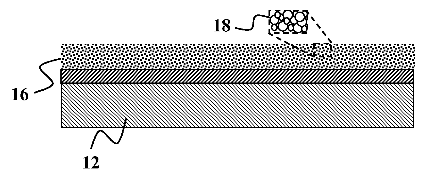
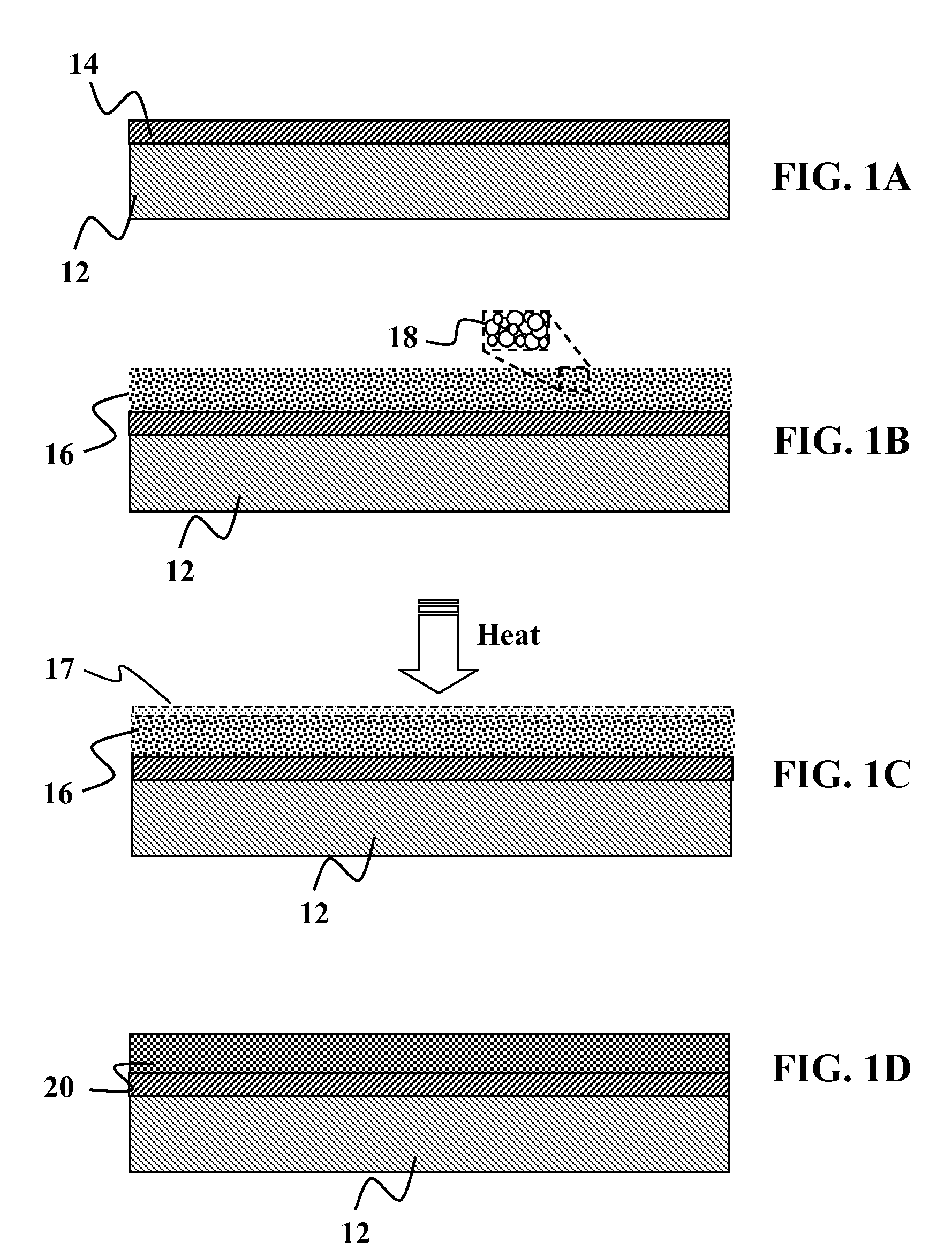
[0009]In one embodiment of the present invention, a photovoltaic roofing assembly is provided that comprises of a roofing membrane and a plurality of photovoltaic cells supported by the roofing membrane. The photovoltaic cells may be lightweight, flexible cells formed on a lightweight foil and disposed as a layer on top of the roofing membrane. The roofing assembly may include at least one flexible encapsulant film that protects the plurality of photovoltaic cells from environmental exposure damage, wherein the encapsulant film is formed using a non-vacuum process. Optionally, the process may be a lamination process. In other embodiments, the process is a non-vacuum, non-lamination process. The resulting roofing membrane and the photovoltaic cells are constructed to be rolled up in lengths suitable for being transported to a building site for unrolling and being affixed to a roof structure.
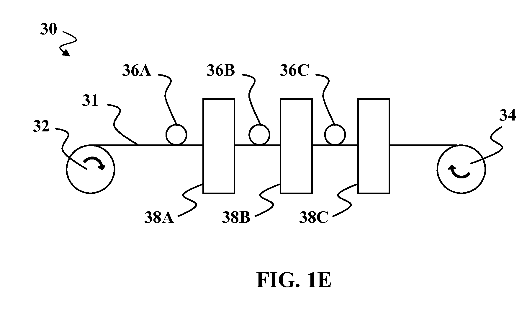
[0012]In a still further embodiment of the present invention, a high throughput manufacturing method comprises providing a plurality of photovoltaic cells, coupling the cells to a roofing membrane; and forming at least one flexible encapsulant film. The encapsulant film is formed to protect the plurality of photovoltaic cells from environmental exposure damage and may be formed using a non-vacuum process. The forming step may be comprised of forming a plurality of discrete nanolaminate layers, wherein the nanolaminate layers self-assemble in a configuration of alternating organic material layers and inorganic material layers. Optionally, the forming step may be comprised of forming a templated nanolaminate barrier film having a plurality of beads with concentric nanolaminate layers about each of the beads, wherein the concentric nanolaminate layers self-assemble about each of the beads. In other embodiments, the forming step may be comprised of forming a fused silica barrier film. Optionally, the forming step may be comprised of forming a polymer-based barrier film. The method may involve using a solution deposition process to form the encapsulant film or using a dry powder process to deposit at least a portion of the encapsulant film.
Problems solved by technology
These electronic devices have been traditionally fabricated using silicon (Si) as a light-absorbing, semiconducting material in a relatively expensive production process.
Although these thin-film based solar cells are known devices, it remains a challenge to cost-effectively produce these cells in sufficient volume with efficiencies greater than or equivalent to their silicon-based counterparts.
Drawbacks associated with these rigid cells, however, make them suboptimal choices for applications that require lightweight and / or flexible devices.
Furthermore, even if such flexible device were efficiently produced, the types of protective encapsulant materials available today are not well suited for use with such flexible solar cells.
However, as discussed above, it is also is heavy, expensive, rigid, and fragile.
However, polymers have poorer barrier qualities and may be permeable to small molecule gases such as water and oxygen.
Polymers may also be difficult to seal to each other at the edges so that gas intrusion is prevented along the plane of a lamination, and many of them are photochemically reactive and degrade in either flexibility or clarity, or both, by ultraviolet exposure over a period of years or even less.
Method used
Image
Click on the blue label to locate the original text in one second.
Reading with bidirectional positioning of images and text.
Examples
Embodiment Construction
[0035]It is to be understood that both the foregoing general description and the following detailed description are exemplary and explanatory only and are not restrictive of the invention, as claimed. It may be noted that, as used in the specification and the appended claims, the singular forms “a”, “an” and “the” include plural referents unless the context clearly dictates otherwise. Thus, for example, reference to “a material” may include mixtures of materials, reference to “a compound” may include multiple compounds, and the like. References cited herein are hereby incorporated by reference in their entirety, except to the extent that they conflict with teachings explicitly set forth in this specification.
[0036]In this specification and in the claims which follow, reference will be made to a number of terms which shall be defined to have the following meanings:
[0037]“Optional” or “optionally” means that the subsequently described circumstance may or may not occur, so that the des...
PUM
Abstract
Methods and devices are provided for improved roofing devices. In one embodiment of the present invention, a photovoltaic roofing assembly is provided that comprises of a roofing membrane and a plurality of photovoltaic cells supported by the roofing membrane. The photovoltaic cells may be lightweight, flexible cells formed on a lightweight foil and disposed as a layer on top of the roofing membrane. The roofing assembly may include at least one flexible encapsulant film that protects the plurality of photovoltaic cells from environmental exposure damage, wherein the encapsulant film is formed using a non-vacuum process. Optionally, the process may be a lamination process. In other embodiments, the process is a non-vacuum, non-lamination process. The resulting roofing membrane and the photovoltaic cells are constructed to be rolled up in lengths suitable for being transported to a building site for unrolling and being affixed to a roof structure.
Description
CROSS-REFERENCE TO RELATED APPLICATIONS[0001]This patent application is a continuation of U.S. patent application Ser. No. 11 / 746,799 filed May 10, 2007 which claims the benefit of priority to commonly assigned, copending U.S. Provisional Application Ser. No. 60 / 746,626 and 60 / 746,629 both filed May 5, 2006; commonly assigned, copending U.S. Provisional Application Ser. No. 60 / 746,961 filed May 10, 2006; commonly assigned, copending U.S. Provisional Application Ser. No. 60 / 804,570 filed Jun. 12, 2006; commonly assigned, copending U.S. Provisional Application Ser. No. 60 / 804,571 filed Jun. 12, 2006; and commonly assigned, copending U.S. Provisional Application Ser. No. 60 / 806,096 filed Jun. 28, 2006. This application is also a continuation-in-part of copending U.S. patent application Ser. No. 11 / 460,613, 11 / 460,617, 11 / 460,618, and 11 / 460,620 all filed one Jul. 27, 2006. This application is also a continuation-in-part of copending U.S. patent application Ser. No. 11 / 462,360 filed Aug...
Claims
Application Information
Patent Timeline
Application Date:The date an application was filed.
Publication Date:The date a patent or application was officially published.
First Publication Date:The earliest publication date of a patent with the same application number.
Issue Date:Publication date of the patent grant document.
PCT Entry Date:The Entry date of PCT National Phase.
Estimated Expiry Date:The statutory expiry date of a patent right according to the Patent Law, and it is the longest term of protection that the patent right can achieve without the termination of the patent right due to other reasons(Term extension factor has been taken into account ).
Invalid Date:Actual expiry date is based on effective date or publication date of legal transaction data of invalid patent.
Patent Type & Authority Applications(United States)