Apparatus and method for collecting and treating waste

a technology for collecting and treating waste materials, applied in the direction of liquid degasification, separation process, borehole/well accessories, etc., can solve the problems of contaminating ground water, material leaching into the ground, and plant life at or around the area where sludge is dumped, etc., to reduce the air pressure within the conduit

Inactive Publication Date: 2012-11-22
HARTLEY DWIGHT
View PDF5 Cites 17 Cited by
  • Summary
  • Abstract
  • Description
  • Claims
  • Application Information

AI Technical Summary

Benefits of technology

[0014]One implementation of the present invention includes a mobile and integrated apparatus for continuously collecting and treating a waste material. The apparatus comprises a delivery mechanism that is configured to continuously move a waste material at a selectable rate through a conduit from a waste site to a motor driven mixing unit. The motor driven mixing unit is configured to mix the waste material with a treating material that can also be introduced to the mixing unit at a selectable rate. The delivery mechanism and the motor driven mixing unit are positioned together on a portable unit so that the mobile and integrated apparatus can be portably stationed at a desired site.
[0015]Another implementation of the present invention includes a mobile and integrated apparatus for continuously collecting and treating a waste material that comprises a motor driven blower that is in fluid communication with a conduit. The blower is configured to decrease the air pressure within the conduit. A separator that is in fluid communication with the conduit is configured to receive a combination of a waste material and air from the conduit and separate the waste material from the air. A motor driven mixing unit that is in fluid communication with the separator continuously receives the waste material from the separator at a selectable rate, along with a treating material that can also be introduced to the mixing unit at a selectable rate. The motor driven blower, the separator, and the motor driven mixing unit are positioned and integrated together on a portable unit (e.g., a trailer or barge) so that the apparatus can be portably stationed at a desired site.

Problems solved by technology

Sludge can be very difficult to handle with conventional equipment.
For example, if the discarded sludge contains salt, plant life at or around an area where sludge is dumped may die.
Further, if the sludge contains hydrocarbons, heavy metals or other toxic materials, these materials may leach into the ground and contaminate ground water.
The chemical mixed into the pool of sludge may convert the mixture into a solid, thereby rendering inert any potentially hazardous materials within the sludge.
This method for treating sludge is problematic for a number of different reasons.
First, the space around a drill site is often limited.
Depending on the depth and size of a borehole, there may not be sufficient space available in the immediate vicinity of a drill site to dig a pit large enough to deposit and treat sludge.
Second, there is a significant potential for environmental contamination.
Third, mixing the chemical thoroughly into the sludge can be difficult.
If not mixed thoroughly, some of the sludge may not be treated and may remain potentially hazardous to the environment.
Further, if the sludge is not mixed completely or if an insufficient amount of or ineffective chemical is used to treat the sludge, the treated mixture may not solidify properly.
There is a potential that a vehicle traveling over or a person walking across such a sludge pit may sink into the pit.
Finally, a pit containing untreated sludge can be a danger to birds and other animals that land on or wander into it.
This fluid is often oily, containing hydrocarbons.
Any bird or other animal that comes into contact with this fluid is likely to be harmed.
As with on-site treatment of sludge, transporting sludge to an off-site facility for treatment is problematic for a number of different reasons.
First, there is a significant potential for environmental contamination.
In addition, there is a potential that the sludge can leak from the container while in transit to the treatment facility.
Second, transporting sludge to an off-site facility requires significant resources, including fuel, time, and manpower.
Because of these dangers, there are federal regulations that limit the weight, volume, and physical condition of sludge that can be transported in one load by a single truck.
Compliance with these regulations often makes the transportation of sludge even more expensive.
Finally, because the space around a drill site is limited, it can be difficult to get trucks into and away from the drill site.
As the distance between the drill site and the trucks increases, the potential for a spill between the drill site and the truck also increases.
The aforementioned problems relating to sludge that are encountered in the drilling industry are also encountered in a number of other industries.
As in drilling operations, waste material in other industries is often in need of treatment before it can be discarded.
Because vacuum trucks are not generally equipped to treat the waste material, once the vacuum truck is full, the truck must transport the waste material to a specialized facility for treatment.
As explained previously, this method for collecting and treating waste materials is problematic.

Method used


Image

  • Apparatus and method for collecting and treating waste
  • Apparatus and method for collecting and treating waste
  • Apparatus and method for collecting and treating waste

Examples


Embodiment Construction

I. Introduction and Definitions

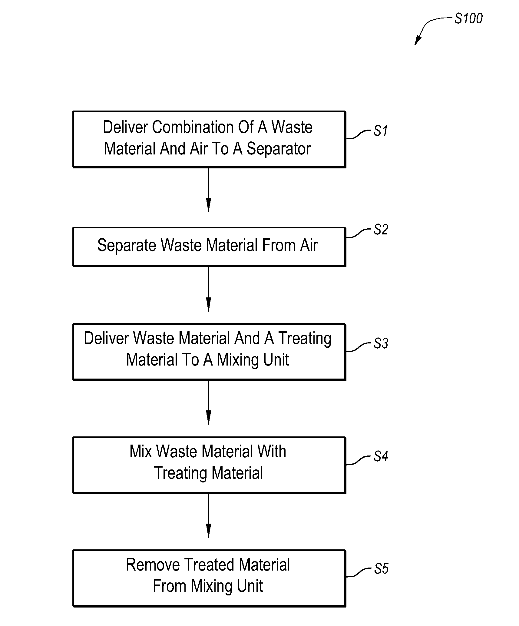
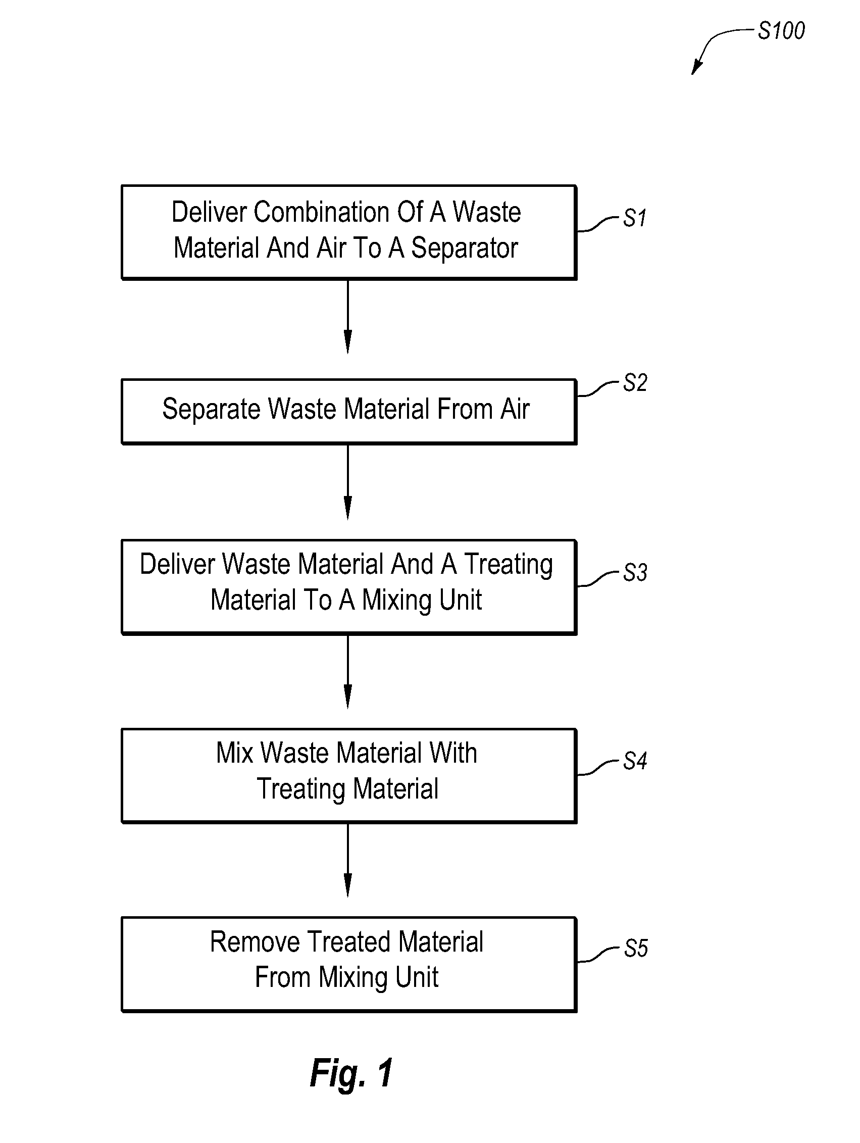
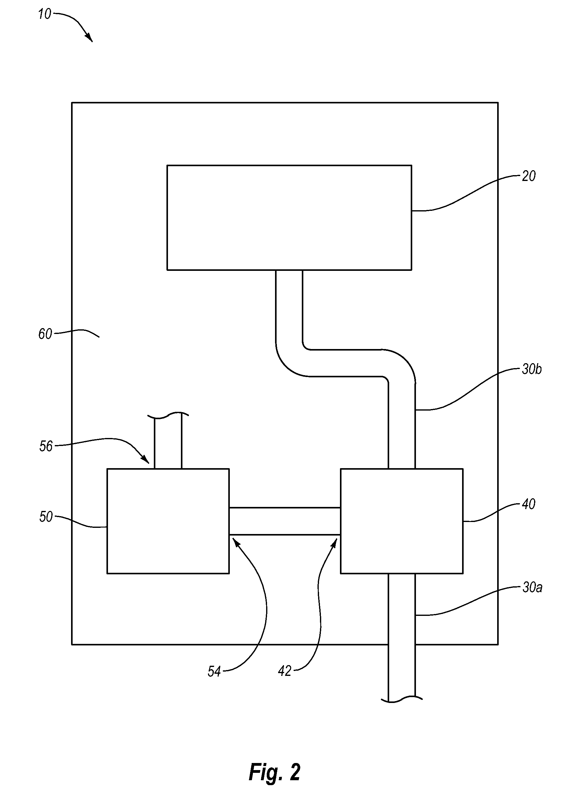
[0028]Implementations of the present invention solve one or more of the problems in the art with an apparatus for collecting and treating waste materials. In particular, one implementation of the present invention includes a mobile and integrated apparatus for continuously collecting and treating a waste material with a portable unit that can be stationed at a waste production site. The present invention also provides methods for collecting and treating waste material with a portable apparatus that continuously collects and treats a waste material.

[0029]Waste material, as that term is used herein, can include any material that requires some form of treatment before it can be disposed of at a landfill, used as a construction fill material, or otherwise discarded. A waste material can include a variety of materials in various forms. For example, a waste material can be wet or dry. A waste material may be a liquid, a solid, a slurry, or a gelatinous subst...


PUM

PropertyMeasurementUnit
distanceaaaaaaaaaa
diameteraaaaaaaaaa
diameteraaaaaaaaaa

Abstract

Devices and methods for collecting and treating waste materials. One implementation of the present invention includes a mobile apparatus that continuously collects a waste material and continuously treats the waste material so that it is suitable for disposal, transportation, or reuse at a desired location. Such an apparatus may include a delivery mechanism that delivers a waste material to a motor driven mixing unit at a selectable rate. This delivery mechanism may include a pump or a motor driven blower and separator. The mixing unit may be configured to receive a treating material and to mix the waste material with the treating material. Advantageously, the delivery mechanism and the mixing unit are positioned together on a portable unit (e.g., a trailer, a barge, a railroad car, etc.) so that the apparatus is mobile and portable.

Description

CROSS-REFERENCE TO RELATED APPLICATIONS[0001]N / A.BACKGROUND OF THE INVENTION[0002]I. The Field of the Invention[0003]The present invention relates generally to methods and devices for collecting and treating waste materials.[0004]II. Background and Relevant Art[0005]In drilling operations, a fluid commonly referred to as “mud” is circulated from the surface, downward through a drill pipe and out openings in the drill bit at the bottom of a borehole. The mud may include hydrocarbons, lubricants and other chemicals that assist in the drilling process. After exiting the drill bit at the bottom of the borehole, the mud along with other material from the borehole (often referred to collectively as “cuttings”), are pushed back upward through the borehole to the surface.[0006]Once at the surface, the cuttings that are extracted from the borehole may be processed in order to separate the mud from the other material. The mud may then be recycled and sent back down the drill pipe, and the mat...

Claims


Application Information

Patent Timeline
Patent Type & Authority Applications(United States)
IPC IPC(8): C02F1/66
CPCC02F1/38B09B3/0025C02F2301/063C02F2201/008B09B3/20B01D19/0052A62D3/33A62D2101/20A62D2101/43A62D2203/10B04C9/00B65G15/00B65G33/14B65G33/26B65G41/002B65G41/007B65G53/24B65G53/60B65G2201/045E21B21/066E21B21/067E21B41/005
Inventor HARTLEY, DWIGHT
Owner HARTLEY DWIGHT
Why Eureka
Try Eureka