Multi-Role Aircraft with Interchangeable Mission Modules

a mission module and multi-role technology, applied in the field of aircraft, can solve the problems of aircraft viability, capital-intensive and usually long process of aircraft development, and each of these prior art approaches has weaknesses

Active Publication Date: 2012-11-22
KAREM ABE
View PDF14 Cites 40 Cited by
  • Summary
  • Abstract
  • Description
  • Claims
  • Application Information

AI Technical Summary

Benefits of technology

[0018]In a first aspect, a modular aircraft combines an originally deployed wing member that provides at least 15% of the lift during at least some portion of cruise flight, a center section that provides at least 25% of the aircraft during such flight, and has one or both of (a) a forward coupling adapted

Problems solved by technology

Aircraft development is a capital-intensive and usually lengthy process.
Further, because the viability of aircraft depend largely on their weight, conservatism in design can have powerful consequences on the viability of an aircraft.
Each of these three prior art approaches has weaknesses.
The first approach, to design a distinct aircraft for a specific mission, is extremely expensive and often impractical.
In general, it has the least potential to meet multiple diverse requirements, therefore limiting its market.
Even this approach is expensive and time consuming, however.
These difficulties arise in part because of formidable certification and qualification requirements.
The third general approach, attempting bridge multiple missions in the design stage through an a priori requirement, often entails extraordinary costs and engineering effort.
Only a few prior art aircraft and aircraft related developments known to the inventor have had elements of modularity, and no known prior art aircraft have achieved complete or even extensive modul

Method used


Image

  • Multi-Role Aircraft with Interchangeable Mission Modules
  • Multi-Role Aircraft with Interchangeable Mission Modules
  • Multi-Role Aircraft with Interchangeable Mission Modules

Examples


Embodiment Construction

[0034]Along with the drawing, the following detailed description serves to elucidate various aspects of the present inventive subject matter.

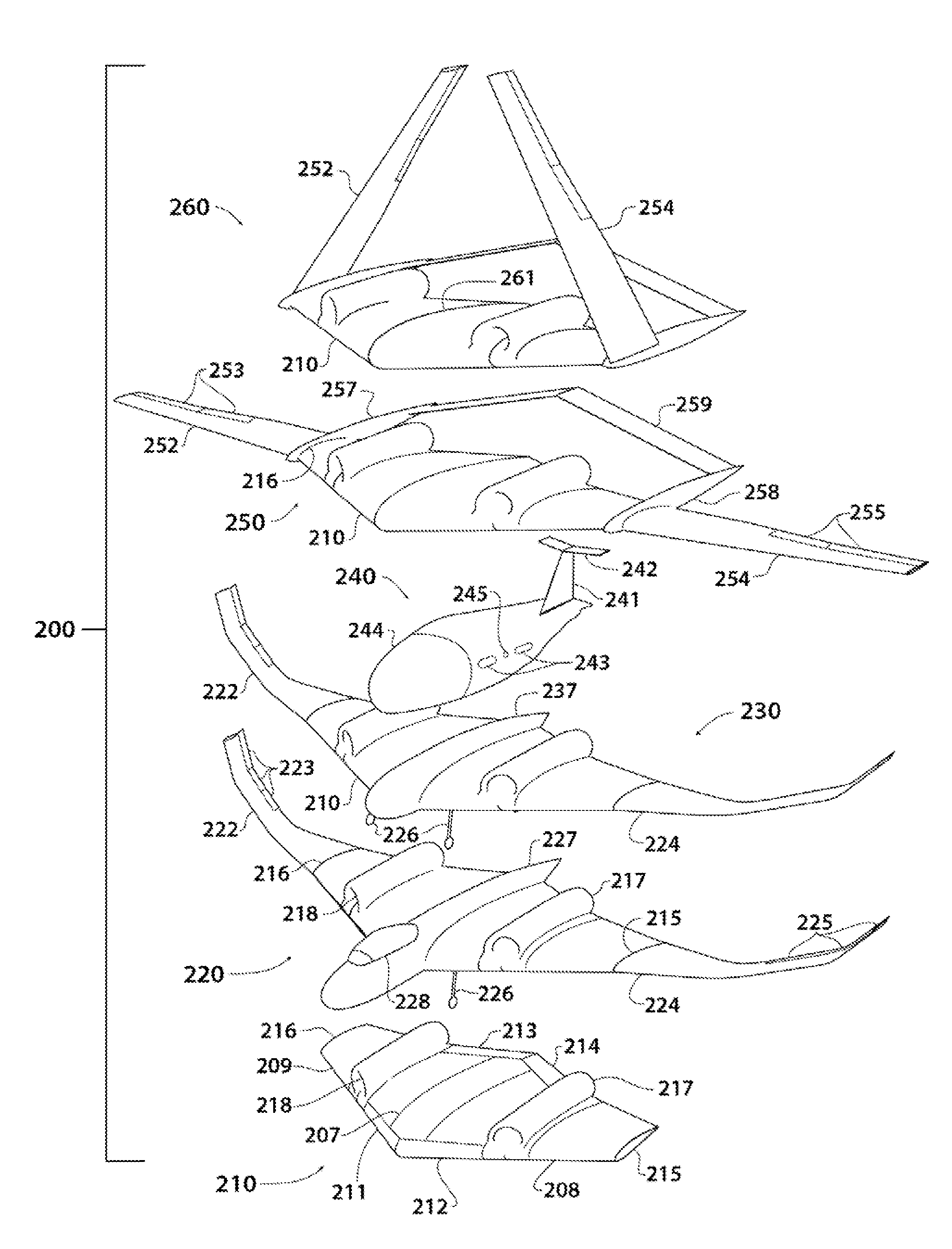
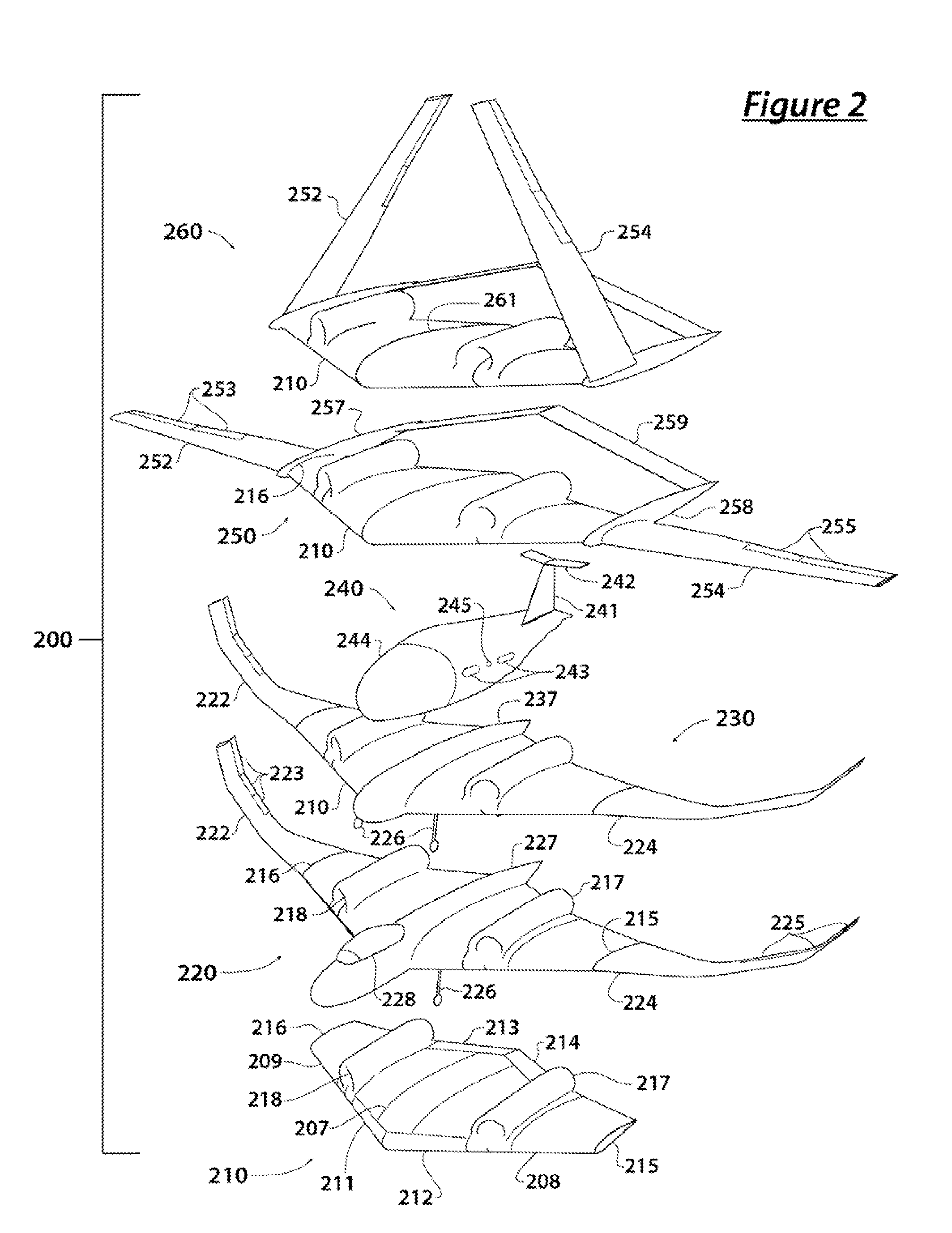
[0035]FIG. 2 is a schematic perspective illustration of a preferred modular aircraft kit comprising a center section, various outer wing portions, and various mission modules.

[0036]The modular aircraft kit 200 comprises a center section 210. The center section 210 advantageously features a left interface 215 for a left outer wing member and a right interface 216 for a right outer wing member. In especially preferred embodiments, the left and right interfaces 215, 216 are hardpoints configured to allow folding or removal of the outer wing members for compact stowage. The center section 210 is preferably equipped with provisions for propulsive means. A right engine housing 218 and a left engine housing 217 each fair over an inlet, turbofan engine, and exhaust. When coupled to electric power, a flight control system, and a fuel supply, the engine ...


PUM


Abstract

A flight-operable, truly modular aircraft has an aircraft core to which one or more of outer wings members, fuselage, cockpit, leading and trailing edge couplings, and empennage and tail sections can be removably coupled and/or replaced during the operating life span of the aircraft. In preferred embodiments the aircraft core houses the propulsive engines, avionics, at least 80% of the fuel, and all of the landing gear. The aircraft core is preferably constructed with curved forward and aft composite spars, that couple to outer wing sections and possibly other sections using hardpoints. The aircraft core preferably has a large central cavity dimensioned to interchangeably carry an ordnance launcher, a surveillance payload, electronic countermeasures, and other types of cargo. Contemplated aircraft can be quite large, for example having a wing span of at least 80 ft.

Description

[0001]This application claims priority to U.S. Provisional Application No. 61 / 372,941 filed Aug. 12, 2010, which is incorporated by reference herein in its entirety.FIELD OF THE INVENTION[0002]The field of the invention is aircraft.BACKGROUND[0003]Aircraft development is a capital-intensive and usually lengthy process. Further, because the viability of aircraft depend largely on their weight, conservatism in design can have powerful consequences on the viability of an aircraft. As a result of these two factors and other considerations, any given aircraft tends to be specialized for one role or mission during the design process.[0004]At the same time, aircraft are used on and needed for a variety of missions and roles. Aircraft carry different payloads, including for example, passengers, cargo, sensors, and munitions. Beyond payload, other requirements can shape an aircraft design; for example, some missions require flight in a certain speed regime, while other missions require high ...

Claims


Application Information

Patent Timeline
IPC IPC(8): B64C39/00B64D11/00B64C5/02B64C25/04B64C3/56B64D7/00B64D27/00B64D47/00B64D37/00B64C1/00B64C1/06
CPCB64C2211/00B64C1/00B64U50/10B64U60/40B64U10/25B64U20/50B64U30/12
Inventor KAREM, ABE
Owner KAREM ABE
Why Eureka
Try Eureka