Charged particle lithography system with intermediate chamber

a lithography system and intermediate chamber technology, applied in the field of chargeable particle lithography apparatus, can solve the problems of reducing the overall throughput of the lithography system, difficulty in attaining high vacuum in the vacuum chamber, and reducing the size, complexity and cost of such systems

a lithography system and intermediate chamber technology, applied in the field of chargeable particle lithography apparatus, can solve the problems of reducing the overall throughput of the lithography system, difficulty in attaining high vacuum in the vacuum chamber, and reducing the size, complexity and cost of such systems

US20120293780A1Active Publication Date: 2012-11-22ASML NETHERLANDS BV

Image

  • Charged particle  lithography system with intermediate chamber
  • Charged particle  lithography system with intermediate chamber
  • Charged particle  lithography system with intermediate chamber

Examples


Embodiment Construction

[0030]The following is a description of various embodiments of the invention, given by way of example only and with reference to the figures. The figures are not drawn to scale and merely intended for illustrative purposes.

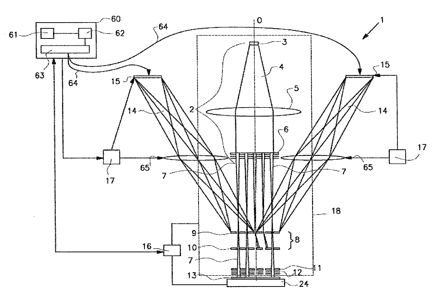
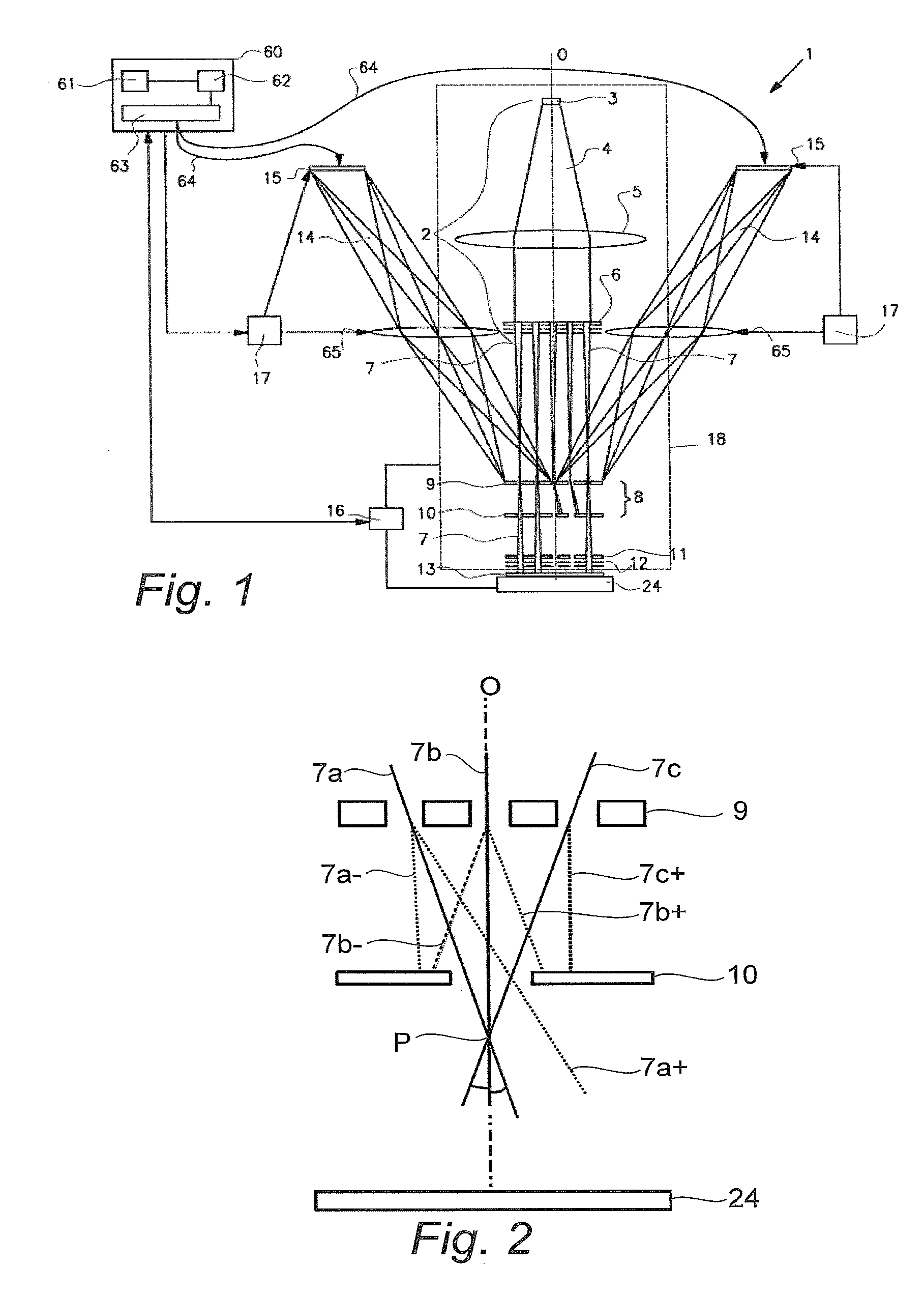
[0031]FIG. 1 shows a simplified schematic drawing of an embodiment of a charged particle multi-beamlet lithography system 1. Such lithography system is for example described in U.S. Pat. Nos. 6,897,458 and 6,958,804 and 7,084,414 and 7,129,502, which are assigned to the applicant of the present application and which are hereby incorporated by reference in their entirety.

[0032]Such lithography system 1 suitably comprises a beamlet generator generating a plurality of beamlets, a beamlet modulator patterning the beamlets to form modulated beamlets, and a beamlet projector for projecting the modulated beamlets onto a surface of a target. The beamlet generator typically comprises a source and at least one beam splitter. The source in FIG. 1 is an electron source 3 arra...


PUM


Abstract

A charged particle lithography system for transferring a pattern onto the surface of a target, comprising a main vacuum chamber, a source chamber and an intermediate chamber, both located in the main vacuum chamber, a beam generator for generating a charged particle beam, the beam generator located in the source chamber, and a first aperture array element for generating a plurality of charged particle beamlets from the beam, the first aperture array element located in the intermediate chamber. The system is adapted for maintaining a first pressure in the main vacuum chamber, a second pressure in the intermediate chamber, and a third pressure in the source chamber, and wherein the first pressure is lower than an ambient pressure, the second pressure is lower than the first pressure, and the third pressure is lower than the second pressure.

Description

BACKGROUND OF THE INVENTION[0001]1. Field of the Invention[0002]The present invention relates to a charged particle lithography apparatus, and in particular to an aperture array for a lithography system with a cooling system.[0003]2. Description of the Related Art[0004]Currently, most commercial lithography systems use a light beam and mask as a means to reproduce pattern data for exposing a target, such as a wafer with a coating of resist. In a maskless lithography system, beams of charged particles are used to write the pattern data onto the target. The beamlets are individually controlled, for example by individually switching them on and off, to generate the required pattern. For high resolution lithography systems designed to operate at a commercially acceptable throughput, the size, complexity, and cost of such systems becomes an obstacle.[0005]Furthermore, existing charged particle beam technology is suitable for lithography systems for relatively course patterning of images,...

Claims


Application Information

Patent Timeline
22 Nov 2012
Publication
US20120293780A1
IPC
G03B27/52
CPC
B82Y10/00; B82Y40/00; H01J37/09; H01J37/16; H01J37/18; H01J37/3174; H01J37/3177; H01J2237/0435
Inventors
DINU-GURTLER, LAURA; URBANUS, WILLEM HENK