Mppt controller, solar battery control device, solar power generation system, mppt control program, and control method for mppt controller

a solar power generation system and control device technology, applied in the direction of electric variable regulation, process and machine control, instruments, etc., can solve the problems of inability to find the optimum power point may be difficult to find, so as to improve the output efficiency of the solar battery

Inactive Publication Date: 2012-11-22
ORMON CORP
View PDF4 Cites 27 Cited by
  • Summary
  • Abstract
  • Description
  • Claims
  • Application Information

AI Technical Summary

Benefits of technology

[0035]This brings about such an effect that that the output efficiency of the solar battery can be improved by performing control by estimated maximum power point even at an unknown power point.
[0037]As described above, an MPPT controller according to the present invention is configured to include: measurement data acquiring means for acquiring environmental data and electric power data, the environmental data being measured values of an environment surrounding a solar battery, the electric power data representing information associated with electric power that is outputted from the solar battery; deriving means for deriving a relational expression that holds between the environmental data and electric power data at the maximum power point thus found; and estimating means for, by using the environmental data measured for the solar battery, estimating the maximum power point from the relational expression derived by the deriving means.
[0038]Further, a control method according to the present invention for an MPPT controller is a method including:

Problems solved by technology

However, MPPT control may, nevertheless, require time to find an optimum power point.
In some cases, it takes several tens of minutes or longer to find an optimum power point.
Frequently, the charac

Method used


Image

  • Mppt controller, solar battery control device, solar power generation system, mppt control program, and control method for mppt controller
  • Mppt controller, solar battery control device, solar power generation system, mppt control program, and control method for mppt controller
  • Mppt controller, solar battery control device, solar power generation system, mppt control program, and control method for mppt controller

Examples


embodiment 1

[0057](Solar Power Generation System)

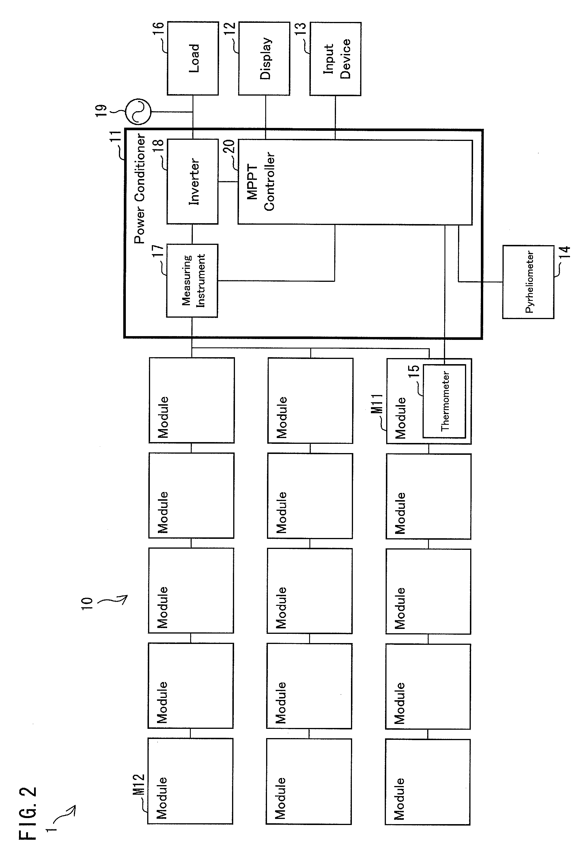
[0058]An embodiment of the present invention is described with reference to FIGS. 1 through 7. As shown in FIG. 2, a solar power generation system 1 is configured to include a solar battery array (hereinafter abbreviated as “array”) 10, a power conditioner (solar battery control device) 11, a display 12, an input device 13, a pyrheliometer (measuring section) 14, a thermometer (measuring section) 15, and a load 16.

[0059]The array 10 is an group of solar battery strings (hereinafter abbreviated as “strings”) connected in parallel, and each of the strings is a group of solar battery modules (hereinafter abbreviated as “modules”) M11 (M12) connected in series. Further, each of the modules M11 (M12) is a group of solar battery cells (hereinafter abbreviated as “cells”), i.e., solar power generation elements, connected in series. Alternatively, each of the modules M11 (M12) may be configured to include a plurality of clusters. The term “cluster” here ...

embodiment 2

[0175]Another embodiment of the present invention is described below with reference to FIGS. 8 and 9. In the present embodiment, a case is described where the MPPT controller 20 provided in the power conditioner 11 of the solar power generation system 1 determines an abnormality in the array 10.

[0176]First, an MPPT controller (power point controller) 21 according to the present embodiment is described with reference to FIG. 8. For convenience of explanation, those members which have the same functions as those already described with reference to the drawings are given the same reference signs, and as such, are not described below.

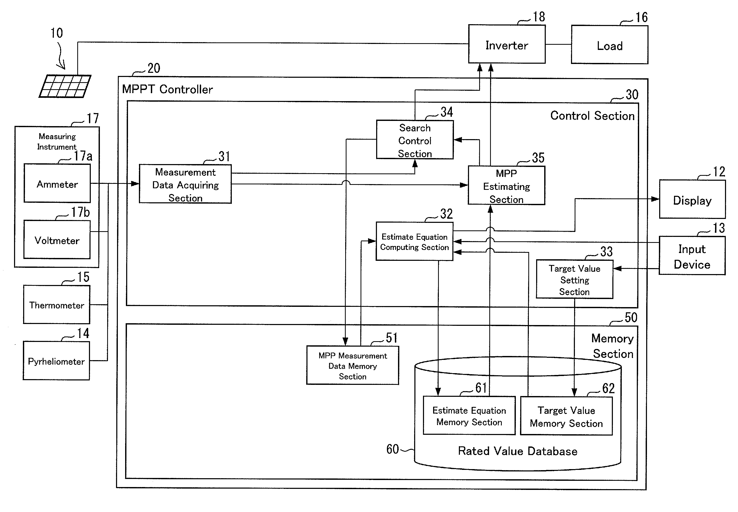
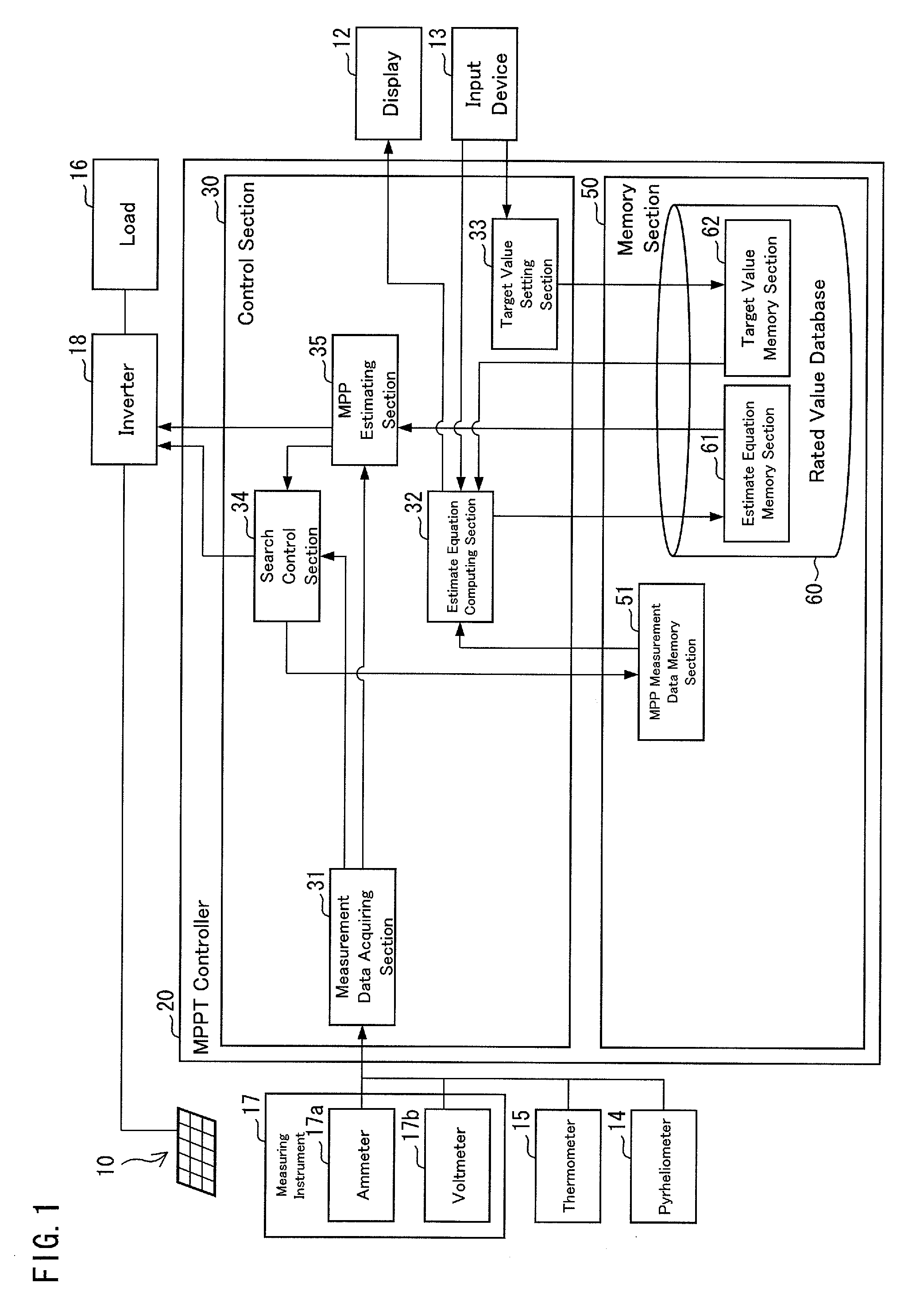
[0177]The MPPT controller 21 is configured by adding an abnormality determining section (abnormal state determining means) 41, a procedure selecting section (search procedure selecting means) 42, and an abnormality determination database 70 to the MPPT controller 20 shown in FIG. 1.

[0178]The abnormality determining section 41 serves determine whether the ou...

embodiment 3

[0219]Still another embodiment of the present invention is described with reference to FIGS. 10 and 11. First, a solar power generation system 2 according to the present embodiment is described with reference to FIG. 10. The solar power generation system 2 differs from the solar power generation system 1 in the following ways.

[0220]First, in the solar power generating system 2, each of the modules includes a DCDC control device (solar battery control device) 80 for controlling a DCDC (direct-current to direct-current) conversion.

[0221]Further, the module M21 is provided with a thermometer 15 so that the surface temperature of the module M21 can be measured, and the thermometer 15 is connected to the DCDC control section 80 of the module M21.

[0222]Each of the DCDC control devices 80 is connected to a pyrheliometer 14, and can acquire measurement data on the amount of solar radiation measured by the pyrheliometer 14. Further, the DCDC control device 80 of the module M22 is connected t...


PUM


Abstract

Even at an unknown power point, control by estimated maximum power point is carried out. An MPPT controller (20) includes: a measurement data acquiring section (31), which acquires an amount of solar radiation and/or a temperature from a pyrheliometer (14)/a thermometer (15), and which acquires an electric current value and/or a voltage value from an ammeter (17a)/a voltmeter (17b); a search control section (34), which searches for a maximum power point by controlling a power point of an array (10) by controlling an inverter (18); an estimate equation computing section (32), which estimates an estimate equation (A) that holds between the amount of solar radiation and a maximum operating current value and/or an estimate equation (B) that holds between the temperature and a maximum operating voltage value; and an MPP estimating section 35, which estimates a maximum power point at an amount of solar radiation or at a temperature by using the estimate equation (A) or (B).

Description

TECHNICAL FIELD[0001]The present invention relates to an MPPT controller, a solar battery control device, an MPPT control program, and a control method for MPPT controller in a solar power generation system including measuring instruments such as a pyrheliometer and a thermometer.BACKGROUND ART[0002]For maximum electric power from a solar power generation system, it is important to efficiently find out the maximum power point (MPP) of a solar battery.[0003]Generally, the output characteristics of a solar battery constituting a solar power generation system vary from hour to hour with the amount of solar radiation, the temperature, etc. For this reason, the solar power generation system is controlled by always monitoring the solar battery so that the solar battery operates at a power point at which the maximum output can be obtained. This control is called MPPT (maximum power point tracking) control.[0004]For efficient MPPT control, a technique has conventionally been proposed which ...

Claims


Application Information

Patent Timeline
IPC IPC(8): G06F19/00G01R31/00
CPCY02E10/58G05F1/67Y02E10/56
Inventor ITOH, HIDEAKI
Owner ORMON CORP
Why Eureka
Try Eureka