

Systems and methods for displaying a unified representation of performance related data
a technology of performance related data and unified representation, applied in the field of modeling and simulation software, can solve the problems of difficult for a person to associate an abstract number, the viewer loses the context of the physical layout of the building, etc., and achieves the effects of reducing the operating cost of the building, improving efficiency, and reducing environmental impa
- Summary
- Abstract
- Description
- Claims
- Application Information
AI Technical Summary
Benefits of technology
Problems solved by technology
Method used
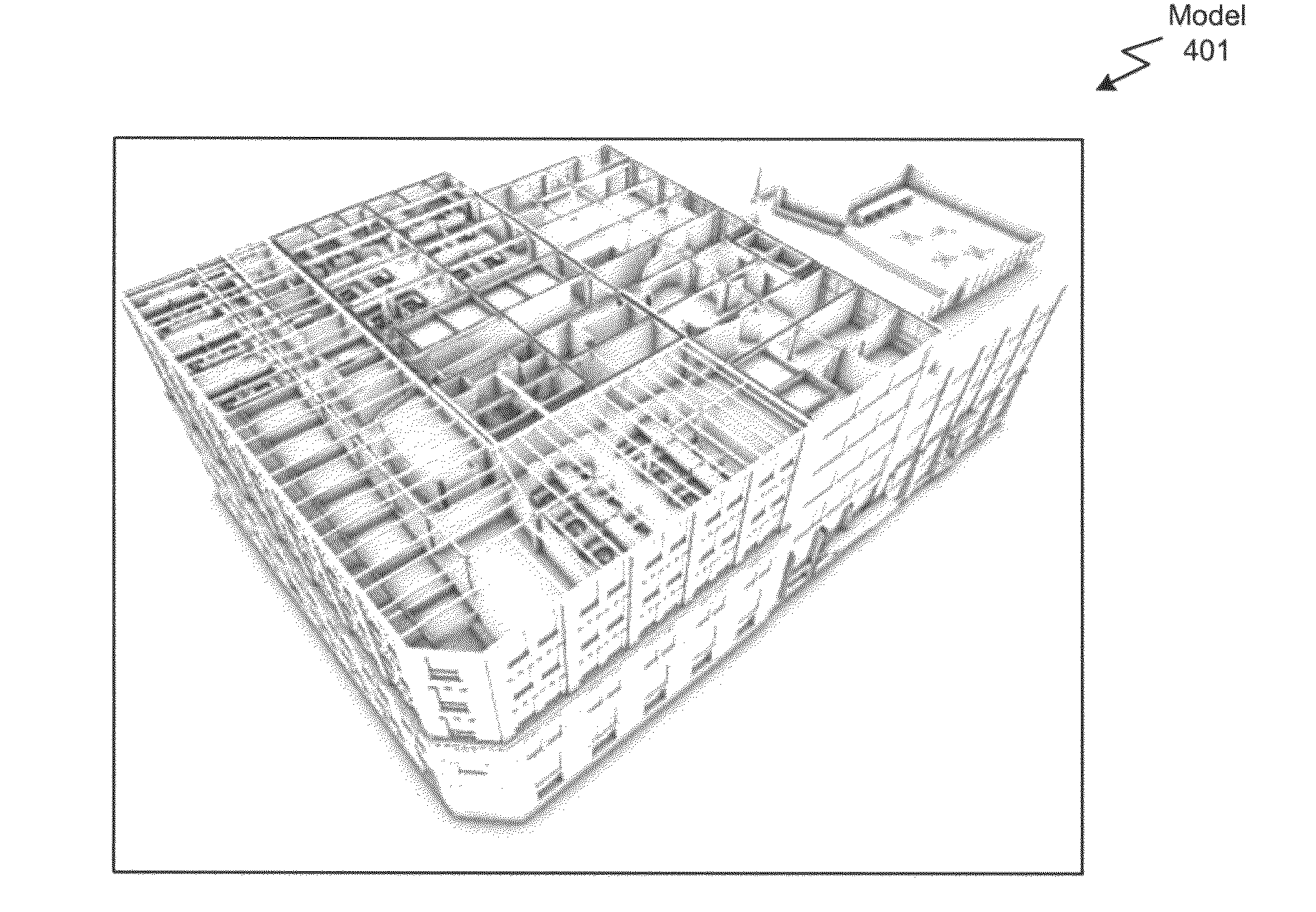
Image

Examples
Embodiment Construction
[0026]In the following description, numerous specific details are set forth to provide a more thorough understanding of the invention. However, it will be apparent to one of skill in the art that the invention may be practiced without one or more of these specific details. In other instances, well-known features have not been described in order to avoid obscuring the invention.
System Overview
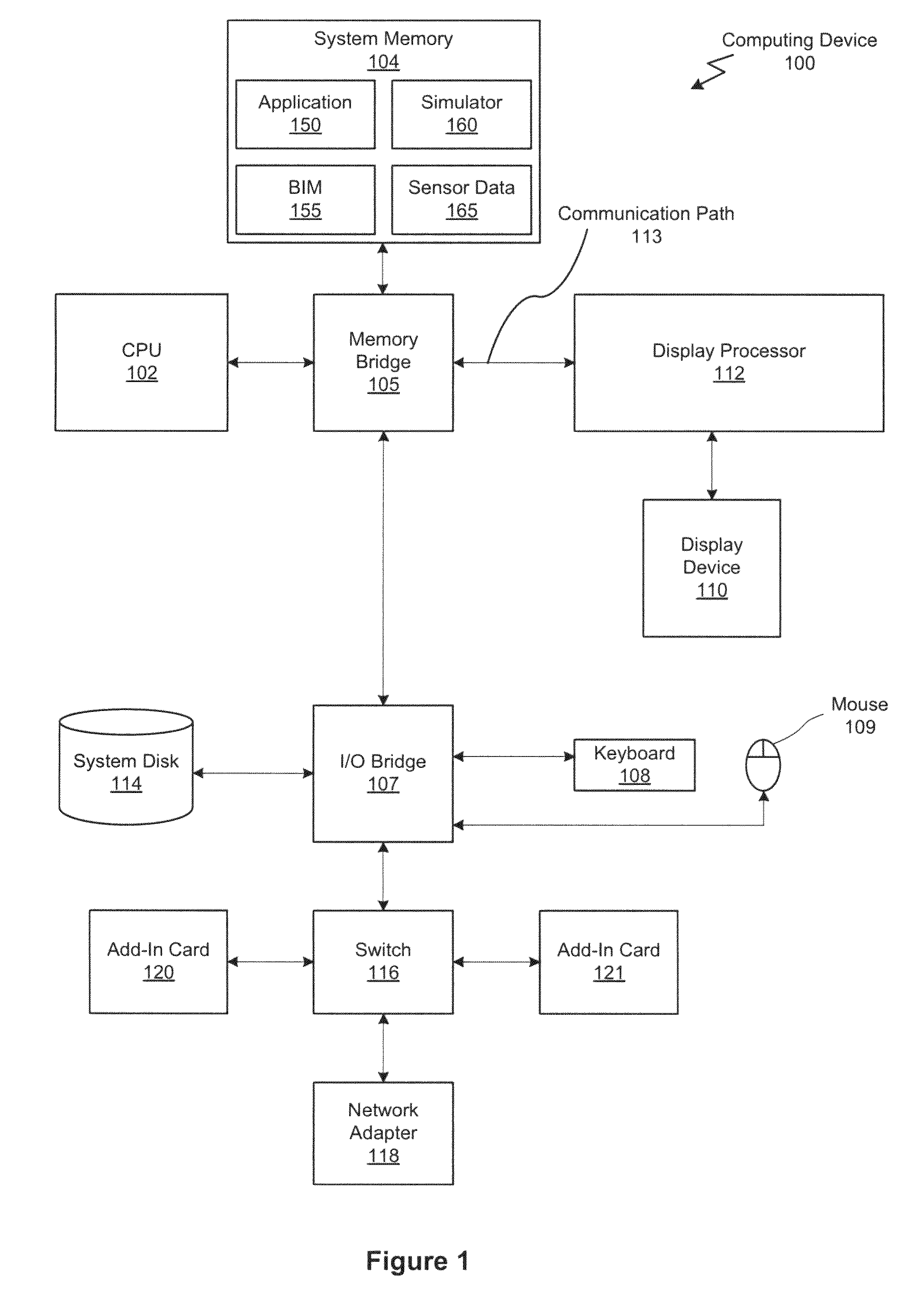
[0027]FIG. 1 is a block diagram of a computing device 100 configured to implement one or more aspects of the present invention. Computing device 100 may be a computer workstation, personal computer, or any other device suitable for practicing one or more embodiments of the present invention. As shown, computing device 100 includes one or more processing units, such as central processing unit (CPU) 102, and a system memory 104 communicating via a bus path that may include a memory bridge 105. CPU 102 includes one or more processing cores, and, in operation, CPU 102 is the master processor of comp...
PUM
 Abstract
Description
Claims
Application Information