
Fluorometric assay apparatus and fluorometric assay method

a fluorometric assay and apparatus technology, applied in the direction of luminescent dosimeters, optical radiation measurement, instruments, etc., can solve the problems of inability to illuminate each wavelength, inability to respect the compact design, and inability to achieve illumination efficiency with respect to each wavelength, so as to achieve the effect of lowering cost and cos

Active Publication Date: 2012-11-29
FUJIFILM CORP
View PDF10 Cites 4 Cited by
  • Summary
  • Abstract
  • Description
  • Claims
  • Application Information

AI Technical Summary

Benefits of technology

[0022]In consideration of the above circumstances, a subject of the present invention is to provide a lower cost fluorometric assay apparatus provided with a light source and excitation filter for exciting plural types of fluorescent stain without switching over filters, and a single long pass filter for detection, and provide a fluorometric assay method of the same.

Problems solved by technology

However, in systems using an ultraviolet fluorescent light lamp that emits a main light band of wavelengths capable of exciting both EtBr and SYBR Green, the excitation efficiency with respect to the fluorescent stain SYBR Green is far from high, and as well as the shortcoming of heat generated by the light source affecting the specimen, there are also disadvantages with respect to compact design.
In the configuration of JP-A No. 2008-145405, since the way the excitation light hits specimens varies depending on the attachment positions of each of the light sources, it is not possible for each wavelength to illuminate equally, and effort is also required to prepare appropriate excitation filters for each light source and to switch them over as required.
In the configuration of JP-A No. 2009-300356, a high cost dichroic filter (interference filter) is used as an excitation light filter in order to illuminate a specimen with two excitation light sources along the same axis, and it is not possible to use a single excitation light filter for plural excitation light sources.
This also has the disadvantage of an increase in the number and types of filter, and the effort for switching over filters.
Operations to switch the light source unit over according to the fluorescent stain used, as described above, force an unnecessary burden on an operator (imaging technician).

Method used


Image

  • Fluorometric assay apparatus and fluorometric assay method
  • Fluorometric assay apparatus and fluorometric assay method
  • Fluorometric assay apparatus and fluorometric assay method

Examples


Embodiment Construction

Relevant Portions

[0062]Explanation follows regarding an exemplary embodiment of the present invention, with reference to the drawings.

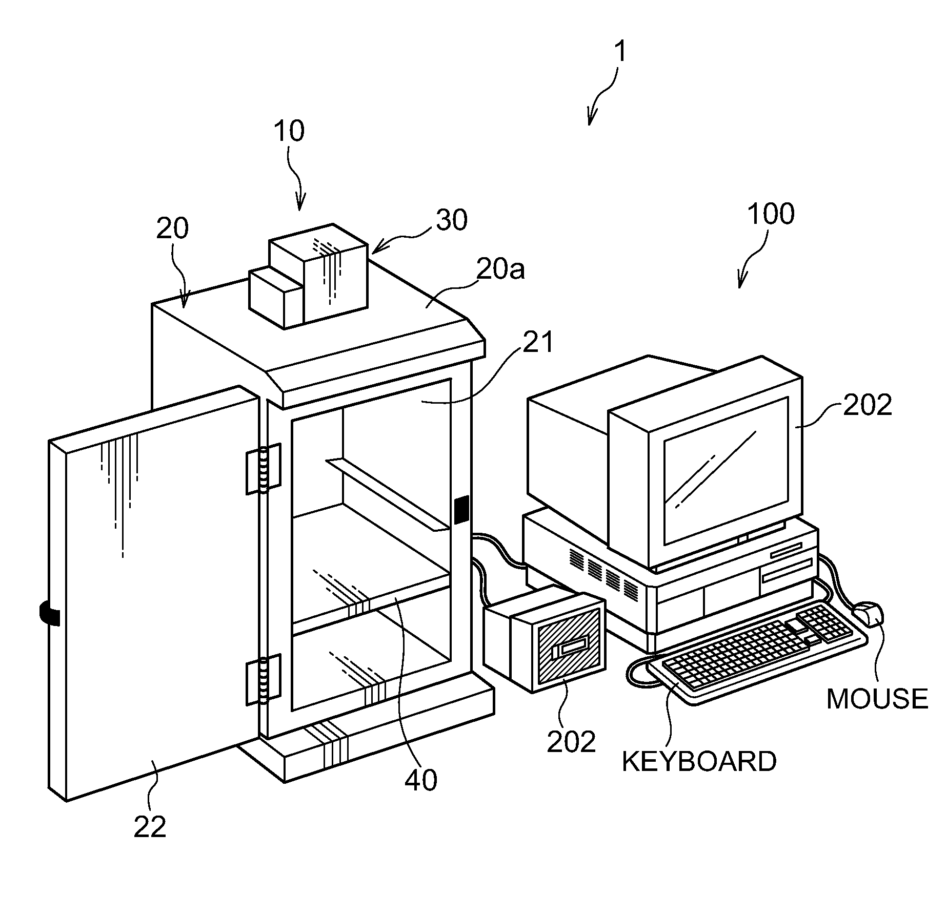
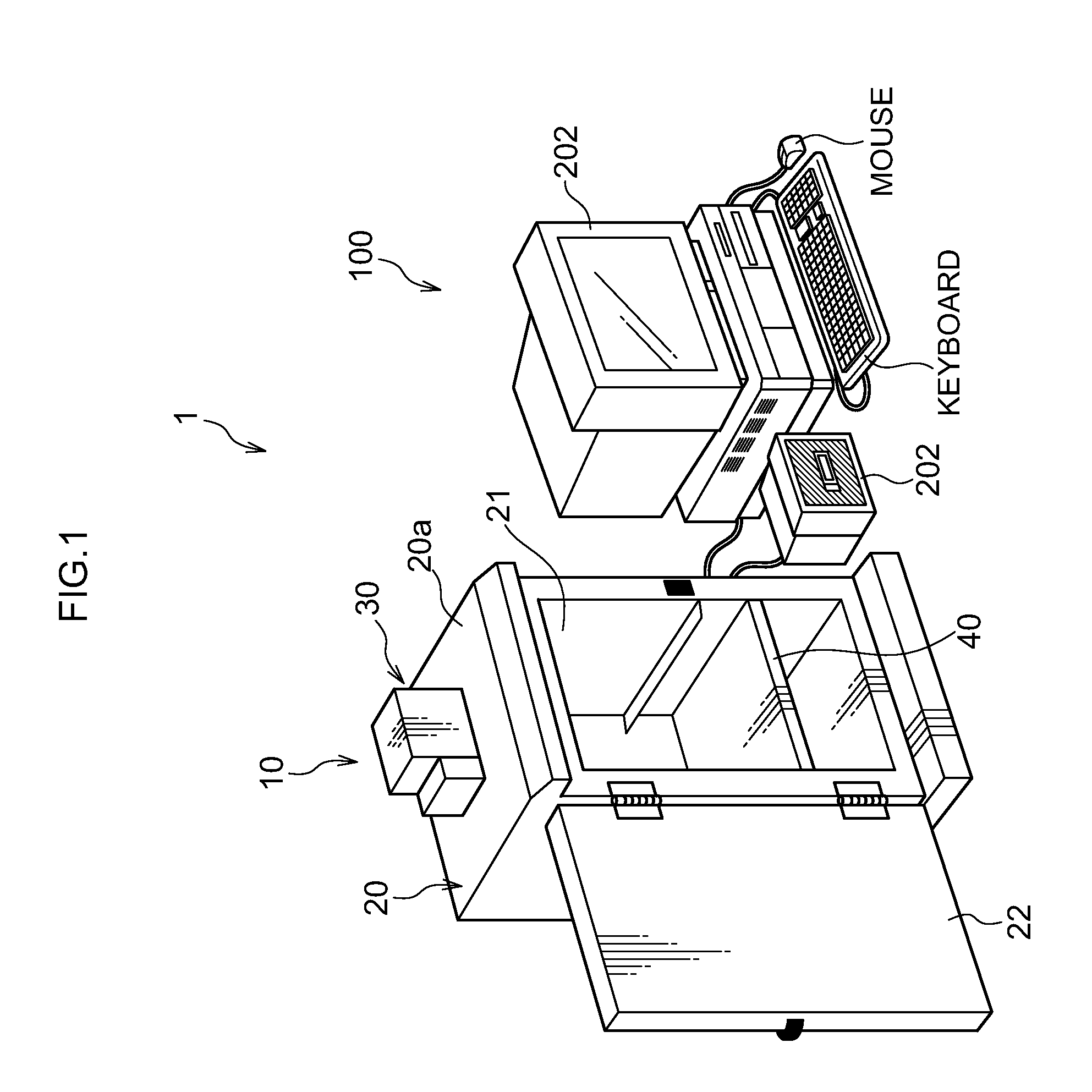
[0063]FIG. 1 is a perspective view showing an example of an imaging system that uses an imaging device relating to the present invention. An imaging system 1 is an imaging system that, depending on the subject, images a subject without illuminating excitation light or by illuminating excitation light, and acquires a captured image of the subject. The imaging system 1 is configured including an imaging device 10 and an image processing device 100.

[0064]The imaging device 10 outputs, to the image processing device 100, image data of the subject that is obtained by imaging the subject. The image processing device 100 subjects the received image data to predetermined image processing as required, and displays the image data on a display 202.

[0065]In the present exemplary embodiment, the subject is a specimen colored with a fluorescent stain (fluorescent l...


PUM


Abstract

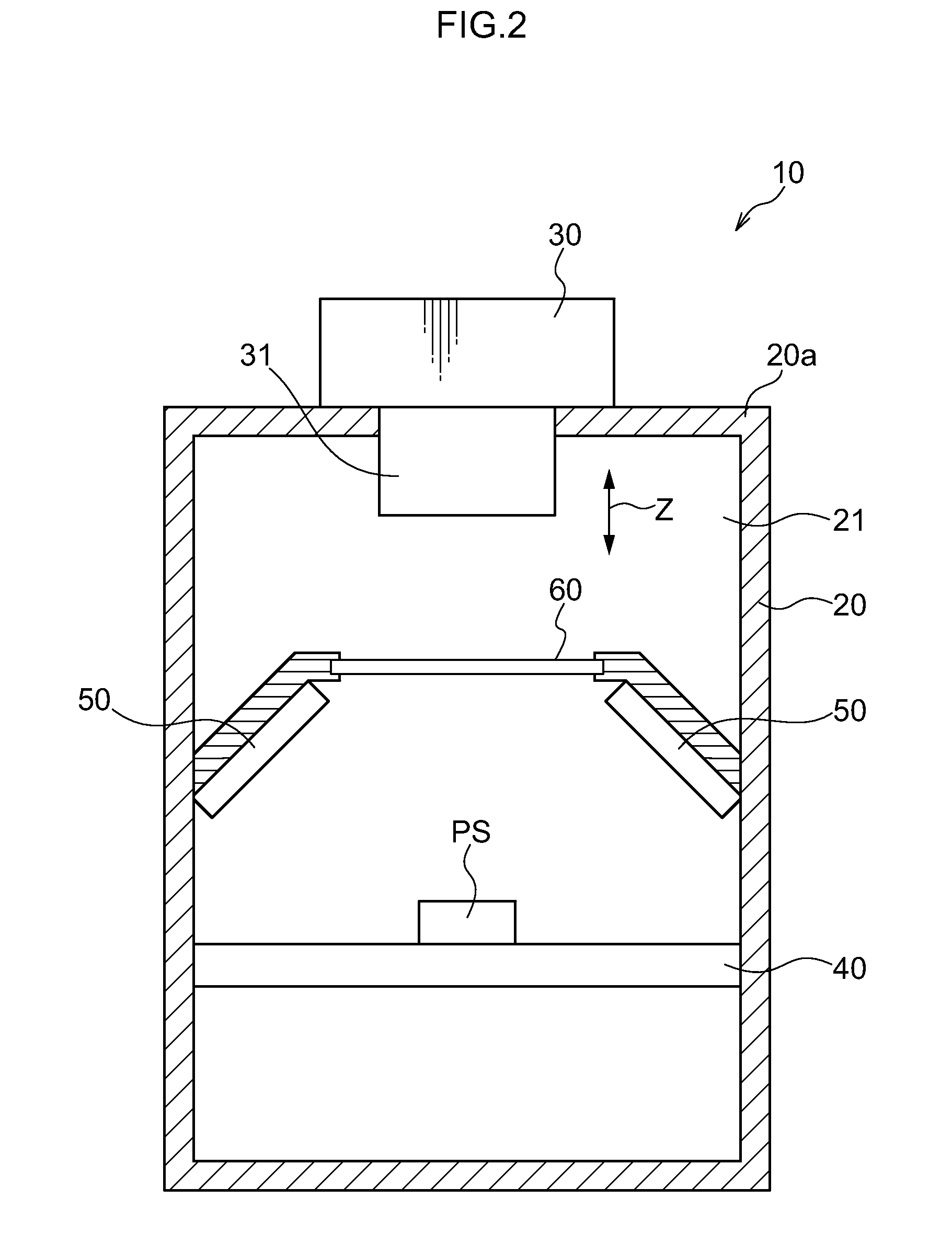
A fluorometric assay apparatus comprising an LED light source configured with at least two types of excitation LED that have different principle wavelengths from each other and are disposed in a two dimensional array on a substrate; an imaging lens for imaging a subject; a single excitation filter provided between the LED light source and a subject, the single excitation filter transmitting each of principle wavelength components of the LED light source; and a single detection long pass filter provided between the imaging lens and the subject.

Description

CROSS-REFERENCE TO RELATED APPLICATION[0001]This application claims priority under 35 USC 119 from Japanese Patent Application No. 2011-117870 filed on May 26, 2011, the disclosure of which is incorporated by reference herein.BACKGROUND OF THE INVENTION[0002]1. Technical Field[0003]The present invention is related to a fluorometric assay apparatus and a fluorometric assay method, and in particular to a fluorometric assay apparatus and fluorometric assay method employing as a light source plural types of LED for generating ultraviolet radiation and visible light.[0004]2. Related Art[0005]In fields of biochemistry, for example as described in Japanese Patent Laid-Open No. 2005-283322, imaging devices are proposed that capture images of subjects such as fluorescent light-emitting specimens marked with fluorescent stains that emit fluorescent light on being illuminated with excitation light or chemical light-emitting specimens that have been placed in contact with a chemical light-emitt...

Claims


Application Information

Patent Timeline
Patent Type & Authority Applications(United States)
IPC IPC(8): G01J1/58G01J3/50
CPCG01N21/6428G01N21/6456G01N2201/0627G01N2021/6441G01N2021/6471G01N2021/6419
Inventor IKAMI, SEISHIMAKINO, KAZUHIRO
Owner FUJIFILM CORP
Learn More