
Multigate structure formed with electroless metal deposition

a multi-layer structure and metal deposition technology, applied in the direction of electrical apparatus, nanotechnology, semiconductor devices, etc., can solve the problems of difficult to achieve epi uniformity, complex and expensive process of epitaxial depositon, and devices are more prone to parasitic resistance, so as to achieve the effect of minimizing parasitic resistan

Inactive Publication Date: 2012-11-29
TAIWAN SEMICON MFG CO LTD +1
View PDF8 Cites 7 Cited by
  • Summary
  • Abstract
  • Description
  • Claims
  • Application Information

AI Technical Summary

Benefits of technology

[0012]electrolessly depositing metallic layer selectively on the side surfaces and top surfaces of the ultra-thin silicon or carbon bodies and on the multigate structures to make electrical contact with the ultra-thin silicon or carbon bodies and to minimize parasitic resistance, wherein the electrolessly deposited metallic layer and ultra-thin silicon or carbon bodies form source and drain regions.
[0016]an electrolessly deposited metallic layer selectively located on the side surfaces and top surfaces of the ultra-thin silicon or carbon bodies and selectively located on top of the multigate structures to make electrical contact with the ultra-thin silicon or carbon bodies and to minimize parasitic resistance, and wherein the ultra-thin silicon or carbon bodies and metallic layer located thereon form source and drain regions.

Problems solved by technology

However, these devices are more prone to parasitic resistance due to the extremely thin Si or carbon (C) body or III-V body (less than 20 nm) and current crowding with the 3-dimensional architectures.
However, epitaxial depositon is a complex and expensive process.
In particular, it is challenging to achieve epi uniform on NFETs and PNFET, and across the wafer.
Moreover, the pre-epi cleans and epitaxial growth conditions are very sensitive to the dopant species, and their concentration at the re-growth interface requires extensive optimization.
In addition, the epi process requires a capping layer on the poly gate (or poly or a-Si portion of high-k metal gates), which requires additional process steps and significantly constrains the device design and process integration.

Method used


Image

  • Multigate structure formed with electroless metal deposition
  • Multigate structure formed with electroless metal deposition
  • Multigate structure formed with electroless metal deposition

Examples


Embodiment Construction

[0020]A more complete appreciation of the disclosure and many of the attendant advantages will be readily obtained, as the same becomes better understood by reference to the following detailed description when considered in connection with the accompanying drawings.

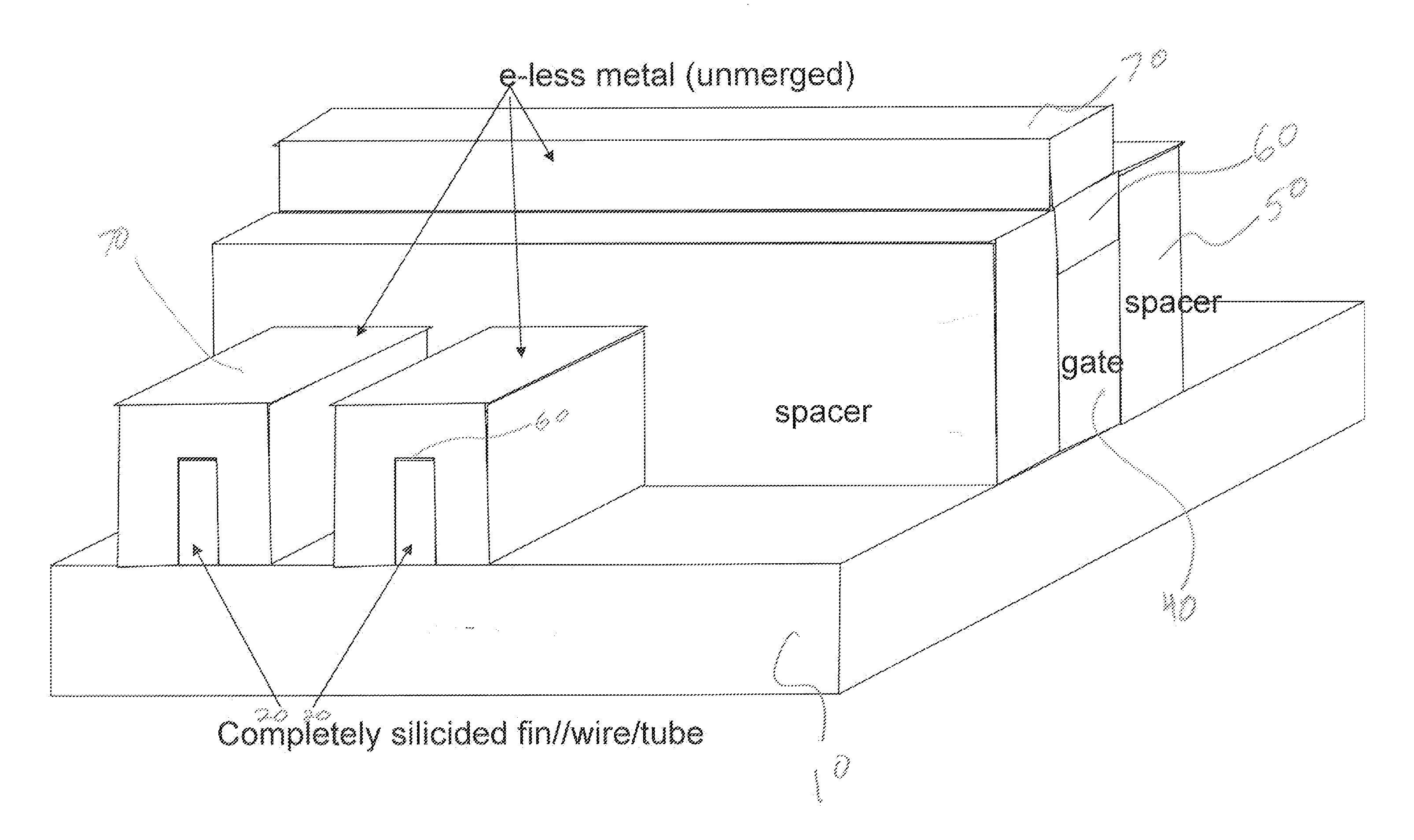
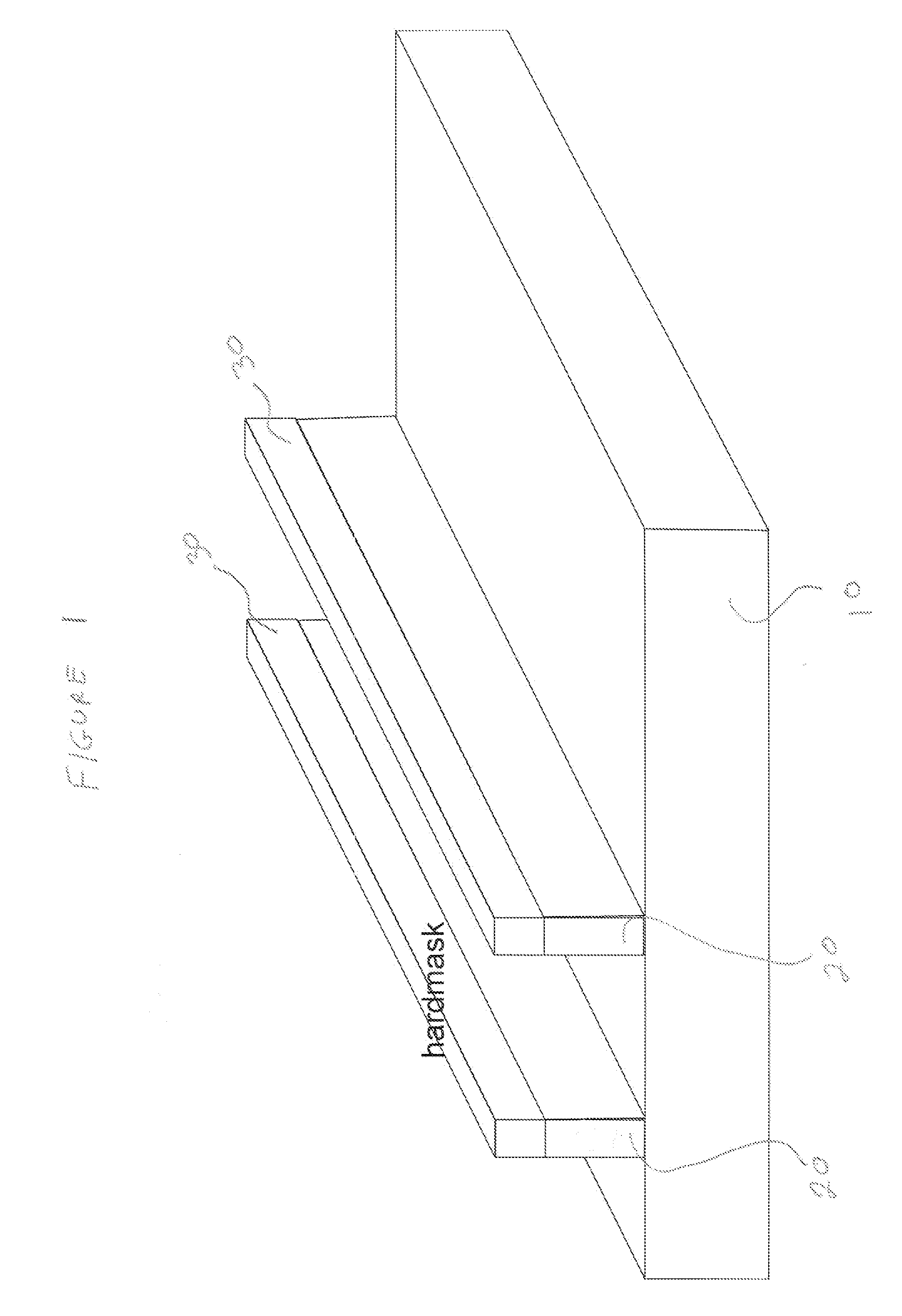
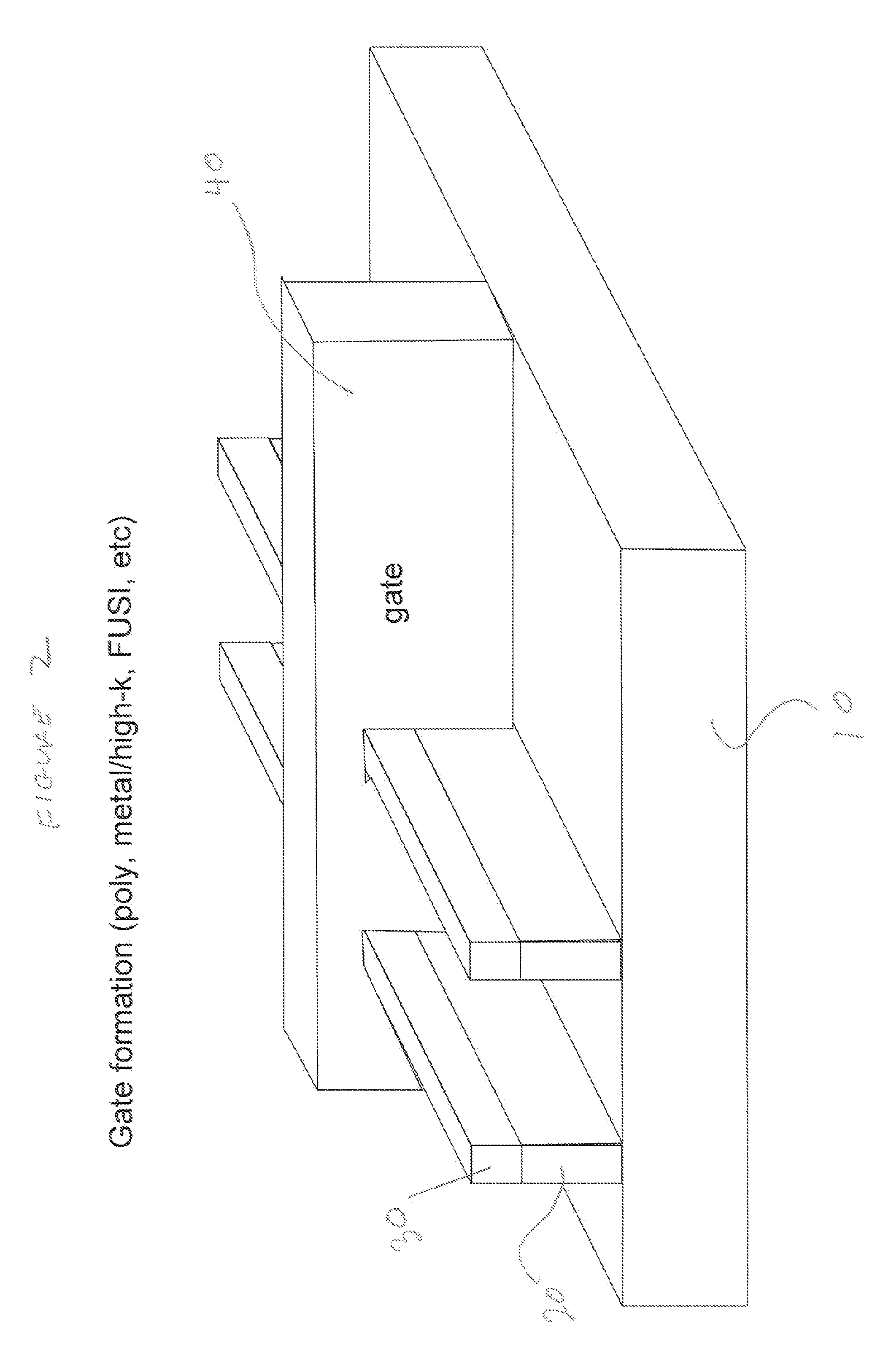
[0021]FIG. 1 illustrates a semiconductor substrate 10 having ultrathin silicon or carbon body 20 delineated thereon and having a hardmask 30 delineated on the top surfaces of fins 20. Examples of substrate 10 include Si, SiC and SOI substrates.

[0022]The ultrathin silicon or carbon body 20 is typically less than 20 nanometers thick and is more typically less than 10 nanometers thick. The ultrathin silicon or carbon bodies 20 are typically fins, nanowires or nanotubes.

[0023]The hardmask layer 30 may be deposited by any process including solution based processes including spin coating, spray coating, dip coating, and scan coating or by vapor deposition processes including chemical vapor deposition, physical deposition, sputt...


PUM

PropertyMeasurementUnit
thickaaaaaaaaaa
thickaaaaaaaaaa
thicknessaaaaaaaaaa

Abstract

A multigate structure which comprises a semiconductor substrate; an ultra-thin silicon or carbon bodies of less than 20 nanometers thick located on the substrate; an electrolessly deposited metallic layer selectively located on the side surfaces and top surfaces of the ultra-thin silicon or carbon bodies and selectively located on top of the multigate structures to make electrical contact with the ultra-thin silicon or carbon bodies and to minimize parasitic resistance, and wherein the ultra-thin silicon or carbon bodies and metallic layer located thereon form source and drain regions is provided along with a process to fabricate the structure.

Description

RELATED APPLICATIONS[0001]This application is a divisional of co-pending application Ser. No. 12 / 955,388, filed on Nov. 29, 2010, and for which priority is claimed under 35 U.S.C. §120, the entire contents of which are hereby incorporated by reference.TECHNICAL FIELD[0002]The disclosure relates to a multigate structure formed with electroless metal deposition on ultra-thin silicon (Si) or carbon or III-V bodies for minimizing parasitic resistance and for making contact to these thin bodies. In particular, the disclosure relates to a selective metal electroless deposition method on the ultra thin Si or carbon (C) body or III-V body (fins, nanowires, or nanotubes), in which the metal is only deposited on a conducting surface such as a silicided area or heavily doped regions.BACKGROUND OF THE DISCLOSURE[0003]In microelectronics, multigate devices such as trigate, finfet, nanowires, and nanotubes have been promising for device scaling due to superior electrostatics. However, these devic...

Claims


Application Information

Patent Timeline
Patent Type & Authority Applications(United States)
IPC IPC(8): H01L29/772B82Y99/00
CPCH01L29/0673H01L21/823814H01L29/41791
Inventor HAENSCH, WILFRIEDLAVOIE, CHRISTIANOUYANG, CHRISTINE QIQINGSHAO, XIAOYANSOLOMON, PAUL M.ZHANG, ZHENYANG, BIN
Owner TAIWAN SEMICON MFG CO LTD
Learn More