Optical packet switching system

a packet switching and optical amplification technology, applied in the field of optical packet switching systems, can solve the problems of inability to extend the transmission distance indefinitely by optical amplification, the optical signal-to-noise ratio (osnr) gets degraded, and the measurement method as with the optical path system cannot be employed to get correct measuremen

Inactive Publication Date: 2012-11-29
FUJITSU LTD
View PDF13 Cites 10 Cited by
  • Summary
  • Abstract
  • Description
  • Claims
  • Application Information

AI Technical Summary

Problems solved by technology

However, the transmission distance cannot be extended indefinitely by optical amplification; an optical signal-to-noise ratio (OSNR) gets degraded whenever the transmission passes through an optical amplifier.
However, there is a problem with the optical packet switching systems that the same measuring method as with the optical path systems cannot be employed to get correct measurement results for reasons peculiar to the optical packets.
Nevertheless, if a conventional measuring method as mentioned above is employed in measuring the optical signal-to-noise ratio, then what will be gained will be a totally meaningless result, such as a mere averaging of the optical signal-to-noise ratios of a plurality of optical packets.
Thus, it will be difficult to measure the optical signal-to-noise ratio of each optical packet which must be measured.
As such, it is difficult to measure the optical noise power on the output side of the optical packet switch, thus making it impossible to measure the optical signal-to-noise ratio.
In actuality, however, these intervals, when they are not short enough, tend to lower the band usage efficiency, so that they are set to very short times of several nanosecond (ns).

Method used


Image

  • Optical packet switching system
  • Optical packet switching system
  • Optical packet switching system

Examples


Embodiment Construction

[0061]The invention will now be described by reference to the preferred embodiments. This does not intend to limit the scope of the present invention, but to exemplify the invention.

[0062]Hereinbelow, optical packet switching apparatuses according to preferred embodiment of the present invention are explained referring to drawings.

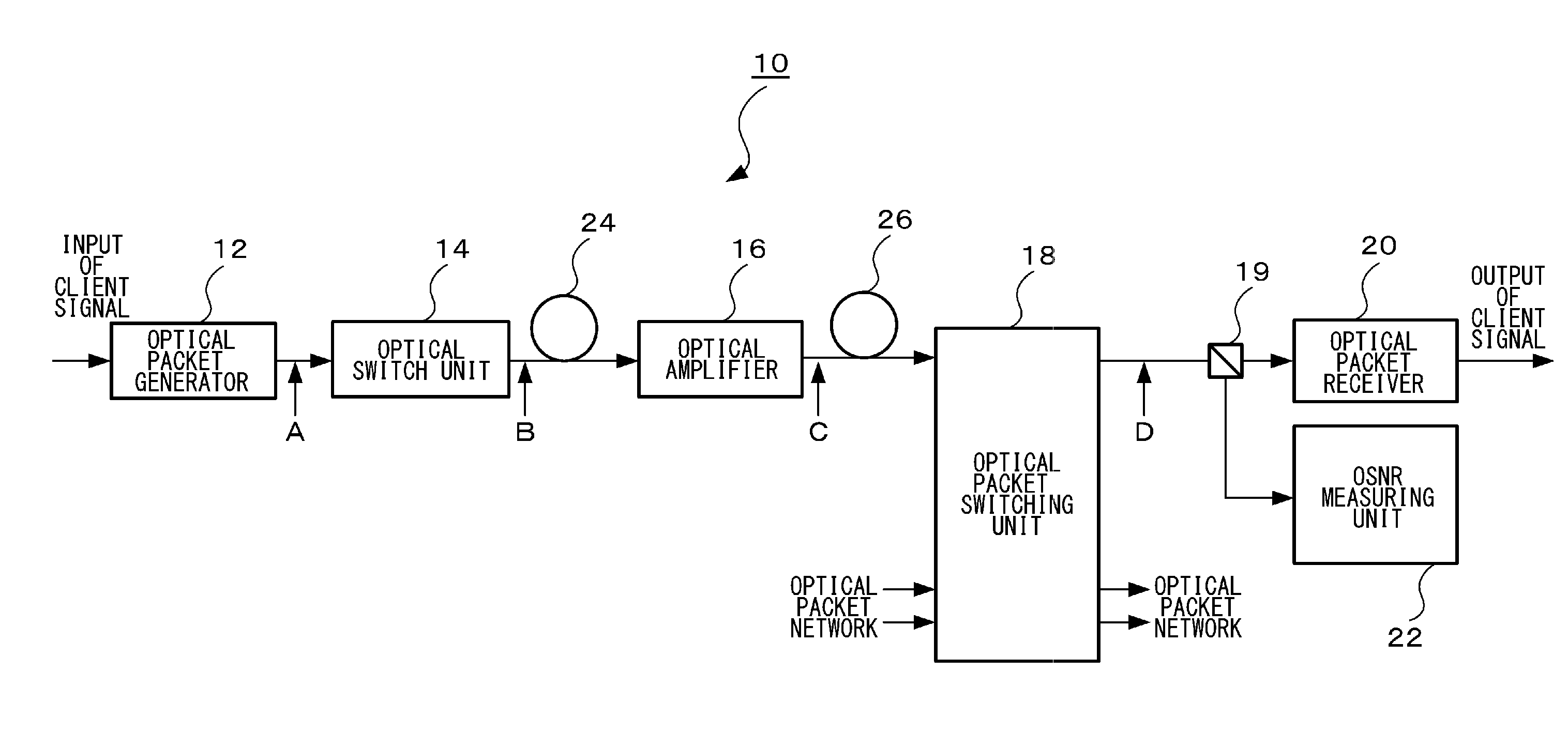
[0063]FIG. 4 shows an optical packet switching system 10 according to an embodiment of the present invention. The optical packet switching system 10 shown in FIG. 4 constitutes a terminal apparatus. An optical packet switching network is configured by connecting a plurality of such terminal apparatuses.

[0064]As shown in FIG. 4, the optical packet switching system 10 includes an optical packet generator 12, an optical switch unit 14, an optical amplifier 16, an optical packet switching unit 18, an optical branching unit 19, an optical packet receiver 20, and an optical signal-to-noise ratio measuring unit 22.

[0065]The optical packet generator 12 generates a...


PUM


Abstract

An optical packet switching system includes an optical packet generator for generating an optical packet signal, an optical packet switching unit, provided with an optical switch, for switching the route of an inputted optical packet signal by controlling on / off of the optical switch, and an optical signal-to-noise ratio measuring unit for measuring the optical signal-to-noise ratio of the optical packet signal outputted from the optical packet switching unit. When switching the route of the optical packet signal, the optical packet switching unit outputs an optical packet signal with optical noise by keeping the optical switch on longer than the time width of the packet signal. The optical signal-to-noise ratio measuring unit measures the optical signal power and the optical noise power, respectively, in the optical packet signal with optical noise and measures the optical signal-to-noise ratio by calculating the ratio between the optical signal power and the optical noise power.

Description

BACKGROUND OF THE INVENTION[0001]1. Field of the Invention[0002]The present invention relates to an optical packet switching system that enables packet switching for each optical packet by switching an optical switch according to destination information given to an optical packet signal.[0003]2. Description of the Related Art[0004]In optical transmission systems employing wavelength division multiplexing (WDM), a technique that performs the path switching per wavelength by the use of a wavelength selective switch (WSS) and the like is put to practical use. As a technology that may succeed this technique, an optical packet switching method is now being investigated. In this optical packet switching method, an IP packet (10 GEther (10 Gigabit Ethernet (registered trademark) signal and the like), for example, is used as a small unit with which the switching is performed, and each is converted into the form of an optical packet and then the route is switched by an ultrahigh-speed optica...

Claims


Application Information

Patent Timeline
Patent Type & Authority Applications(United States)
IPC IPC(8): H04B10/08H04J14/02H04B10/07H04B10/079H04B10/27H04B10/524H04B10/54
CPCH04B10/07953H04Q11/0005H04Q2011/0039H04Q2011/002H04Q11/0066
Inventor MORI, SHOTA
Owner FUJITSU LTD
Why Eureka
Try Eureka