Cutting Insert and Cutting Tool

Inactive Publication Date: 2012-11-29
TUNGALOY CORP
View PDF15 Cites 34 Cited by
  • Summary
  • Abstract
  • Description
  • Claims
  • Application Information

AI Technical Summary

Benefits of technology

[0008]The present invention has been made in view of the above-described problems and has an object to provide a cutting insert having a cutting edge capable of supp

Problems solved by technology

This increase in cutting resistance reduces the life of the cutting edge until the cutting edge becomes worn and becomes unusable and increases the possibility of causing an accidental damage in the cutting boundary portion.
Hence, in the case of the cutting insert having a cutting edge having an arc shape, the d

Method used


Image

  • Cutting Insert and Cutting Tool
  • Cutting Insert and Cutting Tool
  • Cutting Insert and Cutting Tool

Examples


Example

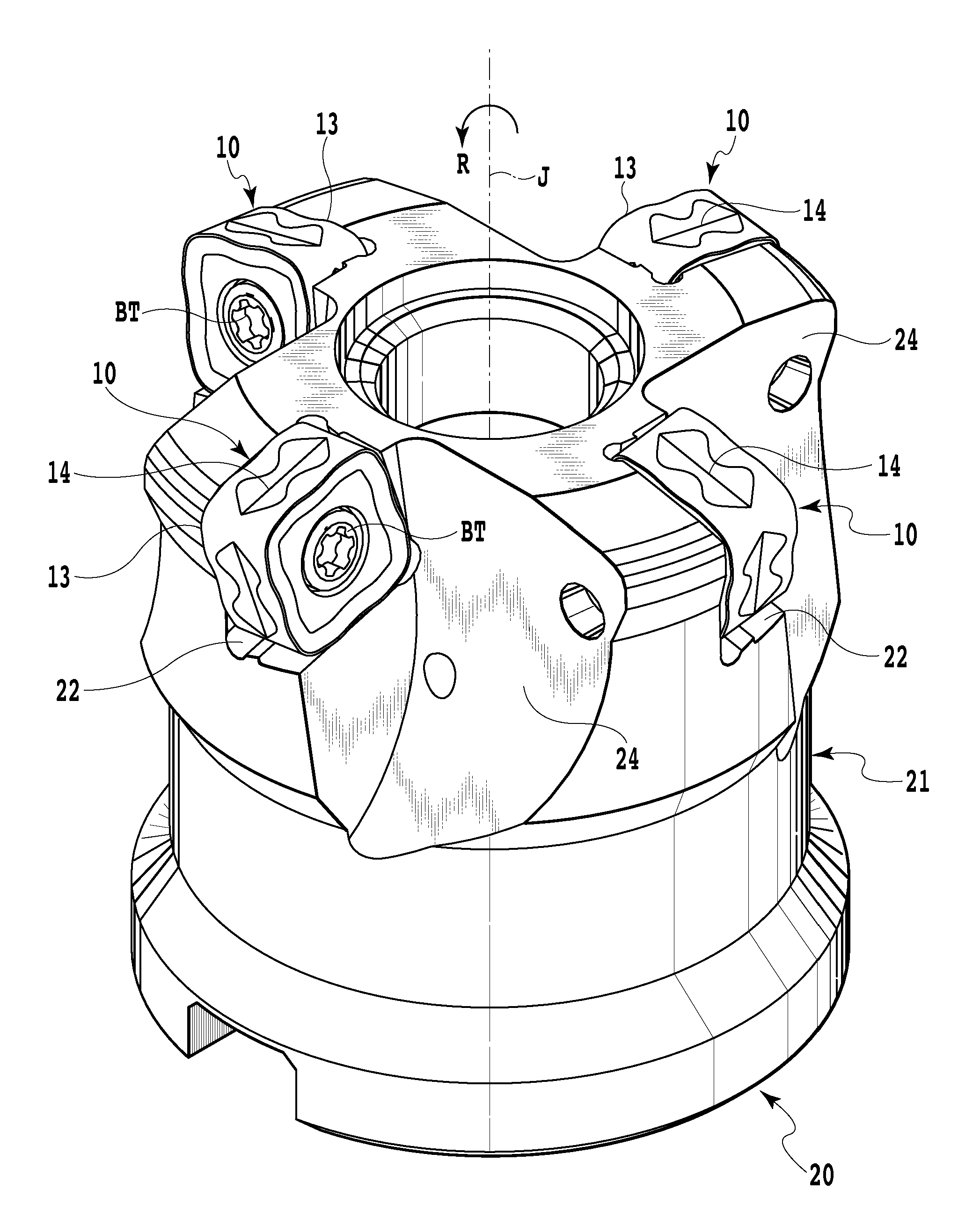
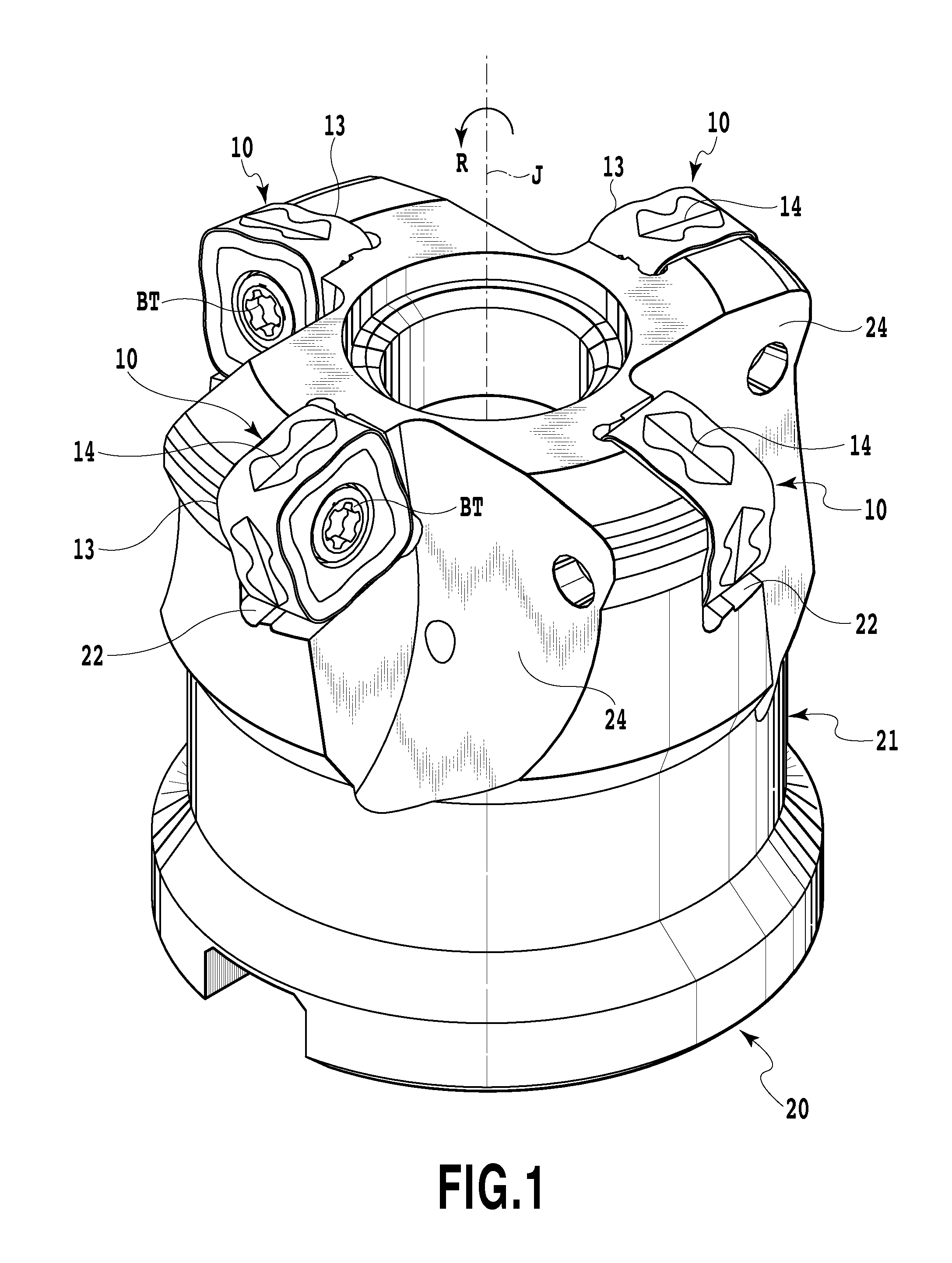
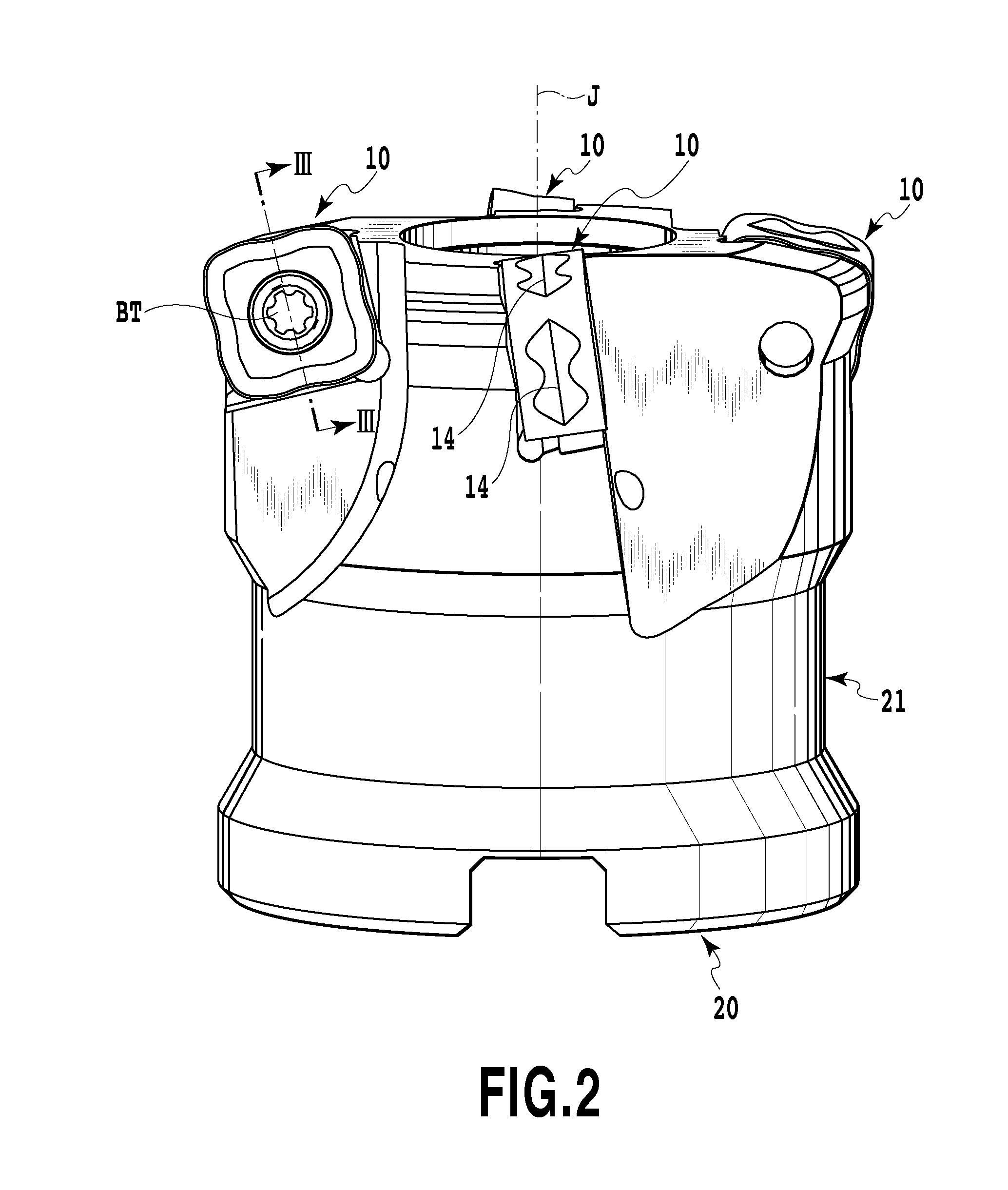
[0033]Hereinafter, an embodiment of the present invention will be described by referring to FIGS. 1 to 8.

[0034]A cutting tool 20 illustrated in FIGS. 1 and 2 is a high-feed cutter and includes a cutting tool body 21 and a plurality of cutting inserts 10.

[0035]The cutting tool body 21 of the cutting tool 20 has, as illustrated in FIG. 4 and the like, an approximately cylindrical shape, and a connecting hole 23 for connecting to a machine tool is provided at the central part thereof, penetrating from a rear end portion to a leading end portion of the cutting tool body 21. In addition, the cutting tool body 21 has a plurality of mounting seats 22 formed at equal intervals in a circumferential direction centering on a tool center axis J. To each of the plurality of mounting seats 22, the cutting insert 10, which will be described later, is attached. The cutting insert 10 is fixed to the cutting tool body 21 by a bolt BT. In front of a rotating direction R of the mounting seat 22 formed ...


PUM

PropertyMeasurementUnit
Angleaaaaaaaaaa
Lengthaaaaaaaaaa
Electrical resistanceaaaaaaaaaa

Abstract

A cutting insert has a cutting edge configured to suppress an increase in cutting resistance applied to a cutting boundary portion with an increase in a depth of cut. The cutting insert has a rake face, a flank, and a cutting edge formed at an intersection portion between the rake face and the flank and is removably attachable to a mounting seat. The cutting edge has an angle decreasing portion in which a cutting edge angle gradually decreases in a direction in which the depth of cut of the cutting edge increases. In one embodiment, the rake face includes an upper rake face and a lower rake face. The flank is formed on a side surface between the top and bottom surfaces. The cutting edge is formed at an intersection portion between the upper rake face and the flank.

Description

RELATED APPLICATIONS[0001]This is a Continuation-in-Part of International Application No. PCT / JP2010 / 054054, filed 10 Mar. 2010 and published as WO 2011 / 111197A1. The contents of the aforementioned application are incorporated by reference in their entirety.BACKGROUND OF THE INVENTION[0002]1. Field of the Invention[0003]The present invention relates to a cutting insert and a cutting tool provided with the same.[0004]2. Description of the Related Art[0005]When a workpiece is machined, an optimal cutting tool in accordance with a type of machining, a material of the workpiece and the like is selected. One of the important elements in selecting a cutting tool is a shape of a cutting edge of a cutting insert actually involved in cutting of the workpiece. For example, when a pocket shape of a die is to be machined, a cutting insert with a cutting edge having an approximately arc shape is used (See Japanese Patent Laid-Open No. 2006-82168), and a cutting insert with a cutting edge having ...

Claims


Application Information

Patent Timeline
IPC IPC(8): B23C5/20B23B27/22B23B27/16
CPCB23C5/06B23C5/2213B23C2200/0422B23C2200/0455B23C2200/128Y10T407/235B23C2200/208B23C2210/168Y10T407/2268Y10T407/24B23C2200/205B23C5/20B23B27/14B23B27/16
Inventor YOSHIOKA, SHIROKONTA, SHIZUE
Owner TUNGALOY CORP
Why Eureka
Try Eureka