Evaporated fuel treating device

Inactive Publication Date: 2012-12-06
AISAN IND CO LTD
View PDF10 Cites 17 Cited by
  • Summary
  • Abstract
  • Description
  • Claims
  • Application Information

AI Technical Summary

Benefits of technology

[0019]According to the present invention, with the space chamber provided between the second adsorbent chamber and the first adsorbent chamber, it can be delayed that a fuel component adsorbed to the second adsorbent chamber or the like is diffused to the first adsorbent chamber. Since the fuel components contain a lot of components heavier than the air, the opening part including the first openings only is provided in the first partition wall and the first openings are provided on the top side of the first partition wall, so as to allow the heavy fuel components to settle down in the space chamber, whereby the fuel components in the gas flowing into the first adsorbent chamber can be reduced. As a result, as compared with the aforementioned conventional canister, the fuel components in the first adsorbent chamber can be lowered, a

Problems solved by technology

Therefore, this conventional canister fails to delay diffusion of ev

Method used


Image

  • Evaporated fuel treating device
  • Evaporated fuel treating device
  • Evaporated fuel treating device

Examples


embodiment 1

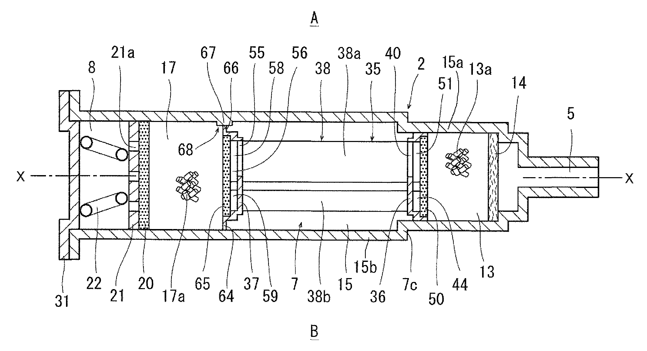
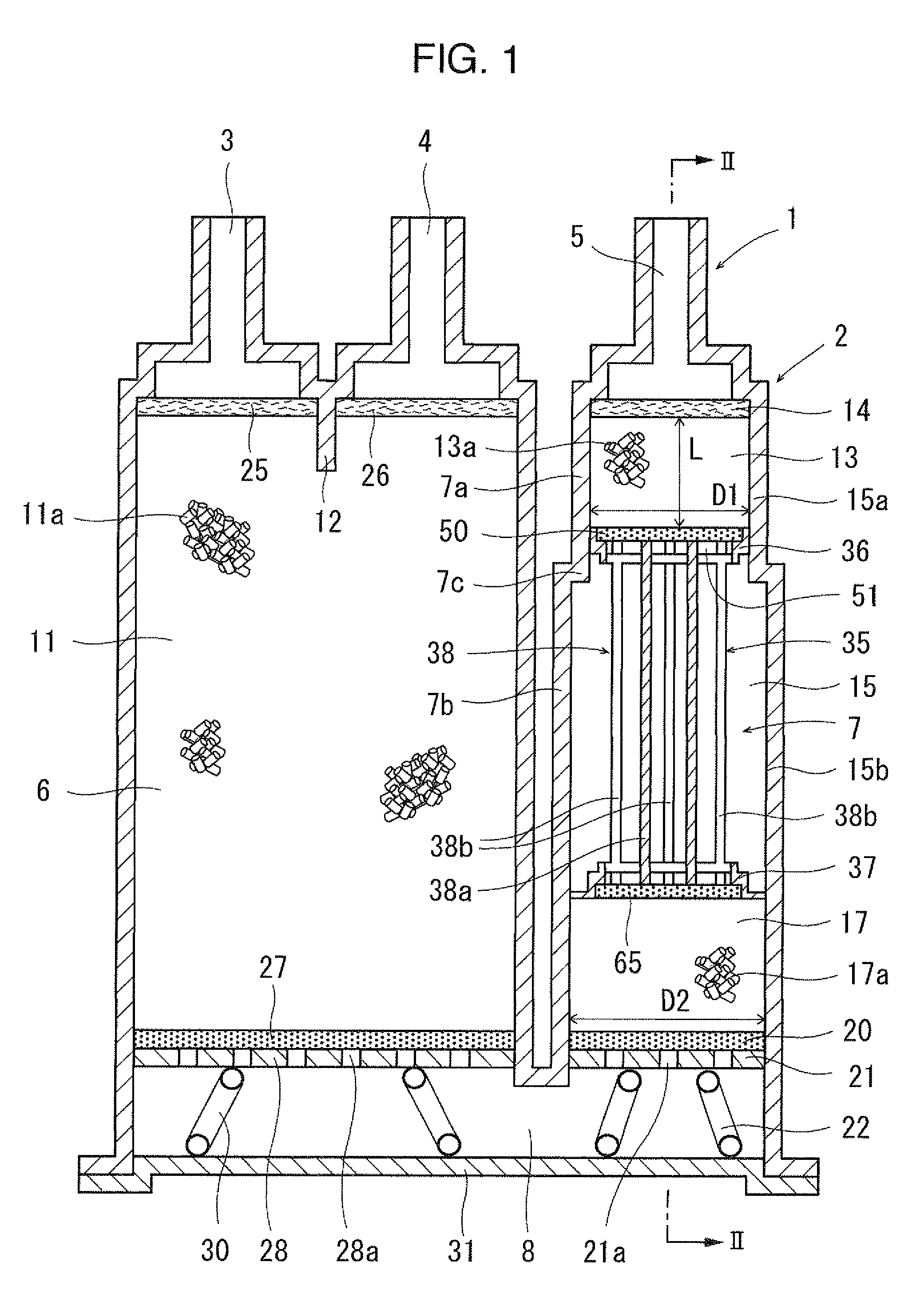
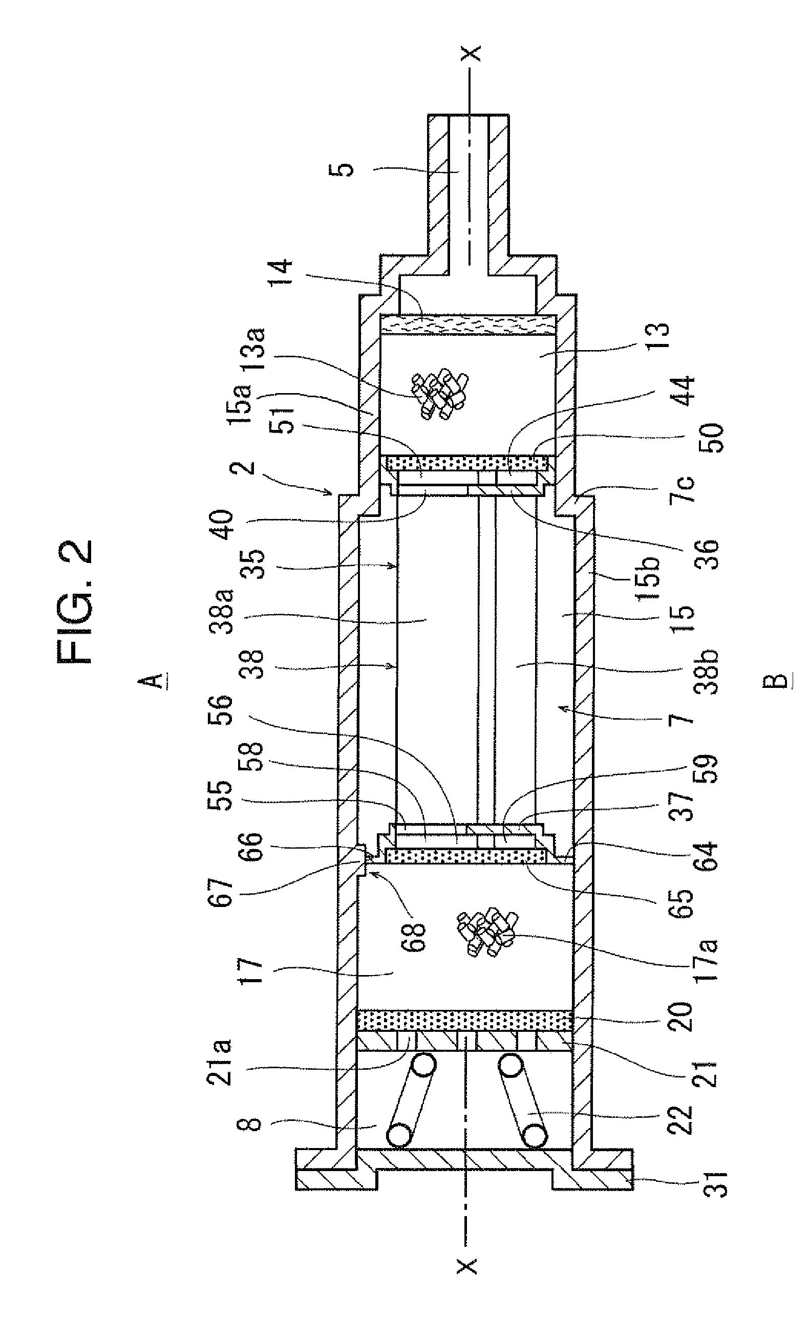
[0041]FIG. 1 to FIG. 8 illustrate Embodiment 1 according to the present invention.

[0042]FIG. 1 schematically illustrates a cross section of a configuration of an evaporated fuel treating device 1 in view of the above, and as illustrated in FIGS. 1 and 2, this evaporated fuel treating device 1 is transversely disposed for use so that a tank port 3, a purge port 4 and an atmospheric port 5 protrude outwardly from one side part of a casing 2. In the following, the upside of FIG. 2 is referred to as a top side A and the downside of FIG. 2 is as a bottom side B for description.

[0043]As illustrated in FIGS. 1 and 2, on one side part of the casing 2 are provided the tank port 3, the purge port 4 and the atmospheric port 5, and in the casing 2 are formed a first housing chamber 6 and a second housing chamber 7, the first housing chamber 6 communicating with the tank port 3 and the purge port 4, and the second housing chamber 7 communicating with the atmospheric port 5. The first housing cha...

embodiment 2

[0088]In Embodiment 1, the filter housing part 49 on the first partition wall 36 side and the filter housing part 62 on the second partition wall 37 side have the same shape, and the filters 50 and 65 have the same size and shape so that one type of components can be used for both of the filters 50 and 65. Instead, as illustrated in FIG. 9, the flange part 64 of Embodiment 1 is not provided, and the second partition wall 37 may have the outer shape abutting on the inner face of the large diameter part 15b of the space chamber 15 and have a size larger than that of the first partition wall 36, and the cylindrical part 57, the filter housing part 62 and the filter 65 on the second partition wall 37 side may be made larger than the cylindrical part 42, the filter housing part 49 and the filter 50 on the first partition wall 36 side, and different types of components may be used for the filters 50 and 65.

[0089]Since the configuration in other points is similar to that in Embodiment 1, t...

embodiment 3

[0090]In Embodiments 1 and 2, the coupling part 38 includes five plate-like members, which are provided in the shapes and at the positions as illustrate in FIGS. 5 to 8. Instead of the plate-like members, a coupling member of any shape such as a cylindrical column or a polygonal prism such as a quadrangular prism or a hexagonal column may be provided as the coupling part 38, the coupling member may be provided at any position or the coupling members in any number may be set to make up the coupling part 38 as long as a constant distance between the first partition wall 36 and the second partition wall 37 can be kept.

[0091]Although the top-side coupling members 38a as a part of the coupling part 38 is used as current plates, a current plate may be provided as a member different from the coupling part 38. As long as such the current plate may have one end positioned between adjacent first openings 40 and 40, and a surface and a rear face thereof may be positioned along the top and bott...


PUM

PropertyMeasurementUnit
Volumeaaaaaaaaaa
Currentaaaaaaaaaa
Areaaaaaaaaaaa

Abstract

An evaporated fuel treating device lowers the blow-by volume of evaporated fuel emitted to the atmosphere via a casing having an atmospheric port. The casing has in series a first adsorbent chamber housing an adsorbent material, a space chamber not housing an adsorbent material and a second adsorbent chamber housing an adsorbent material. Each of the chambers is positioned beside an adjacent chamber thereof. The first chamber is disposed closest to the atmospheric port among the adsorbent chambers. An end part of the space chamber on a side of the first chamber has a first partition wall having an opening part with a plurality of first openings provided on a top side of the first partition wall. A current plate has one end positioned between the adjacent first openings and a surface and a rear face of the current plate are disposed along the top and bottom direction.

Description

BACKGROUND OF THE INVENTION[0001](1) Field of the Invention[0002]The present invention relates to an evaporated fuel treating device.[0003](2) Description of Related Art[0004]Conventionally, an evaporated fuel treating device (hereinafter this may be called a canister) is used to temporarily adsorb a fuel component in evaporated fuel so as to prevent emission of the evaporated fuel from a fuel tank of a vehicle or the like to the atmosphere.[0005]In recent years, a canister is required to reduce the diffusion amount of evaporated fuel to the atmosphere. As a canister with less diffusion amount of evaporated fuel to the atmosphere, a canister 101 as illustrated in FIG. 19 is known, including a casing 105 provided with a tank port 102, a purge port 103 and an atmospheric port 104. In the casing 105 are formed a first housing chamber 106 and a second housing chamber 107, the first housing chamber 106 communicating with the tank port 102 and the purge port 103, and the second housing ch...

Claims


Application Information

Patent Timeline
IPC IPC(8): B01D53/02
CPCF02M25/0854B01D53/0407B01D2253/102B01D2257/702B01D53/0446B01D2259/403B01D2259/41B01D2259/4516B01D2259/4145B01D2259/40086
Inventor SUGIURA, MASANORITESHIMA, HIDEKIKURATA, TSUNEYUKIBUSEKI, NAOHITO
Owner AISAN IND CO LTD
Why Eureka
Try Eureka