Combined integration and pulse detection

Active Publication Date: 2012-12-06
CAELESTE CVBA +1
View PDF0 Cites 45 Cited by
  • Summary
  • Abstract
  • Description
  • Claims
  • Application Information

AI Technical Summary

Benefits of technology

[0011]It is an object of embodiments of the present invention to combine the advantages o

Problems solved by technology

However, such counting pi

Method used


Image

  • Combined integration and pulse detection
  • Combined integration and pulse detection
  • Combined integration and pulse detection

Examples


first embodiment

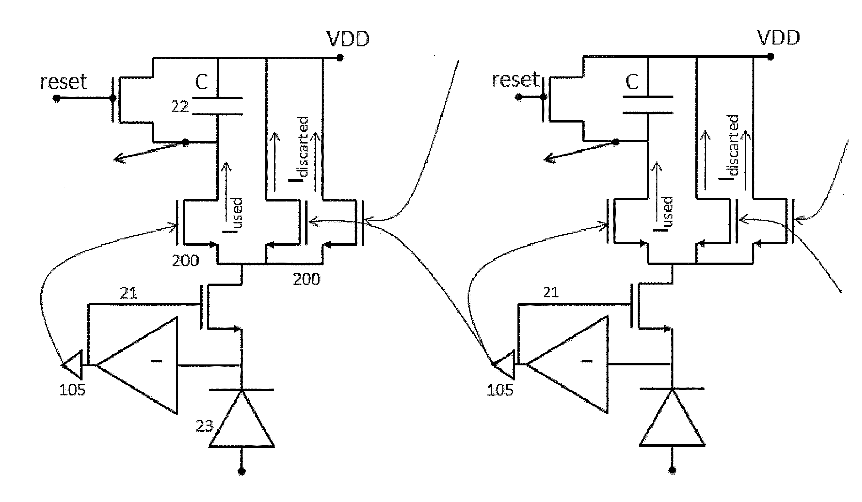
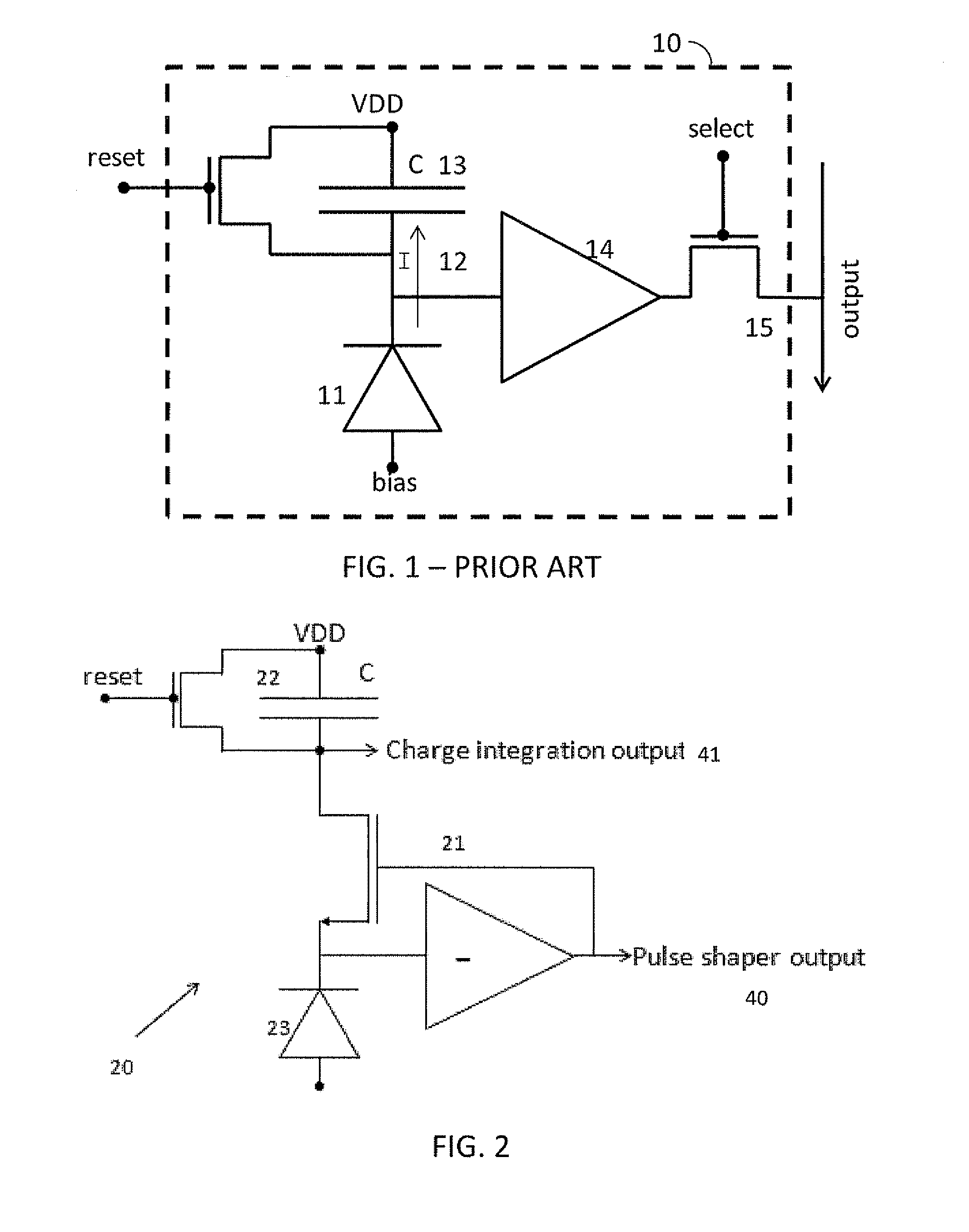
[0069]A general pixel 20 according to the present invention is illustrated in FIG. 2. A pixel 20 is illustrated, with one pulse detector, for example implemented as a pulse shaper circuit 21, and one integrator 22, both acting upon and in series with a same signal current emanating from a radiation transducer or charge input, represented here as a (photo)diode 23. Not illustrated in FIG. 2 are further pixel circuit elements as buffers, multiplexers, accumulators, etc. The pixel 20 has two output ports, for each delivering an output signal: a pulse shaper output signal 40 and a charge integration output signal 41.

The Pulse Detection Circuit

[0070]With the pixel comprising “at least one pulse detection circuit” is meant that the pixel has a provision to create a transient electrical pulse to indicate the passage or detection of a particle, photon, charge packet etc.

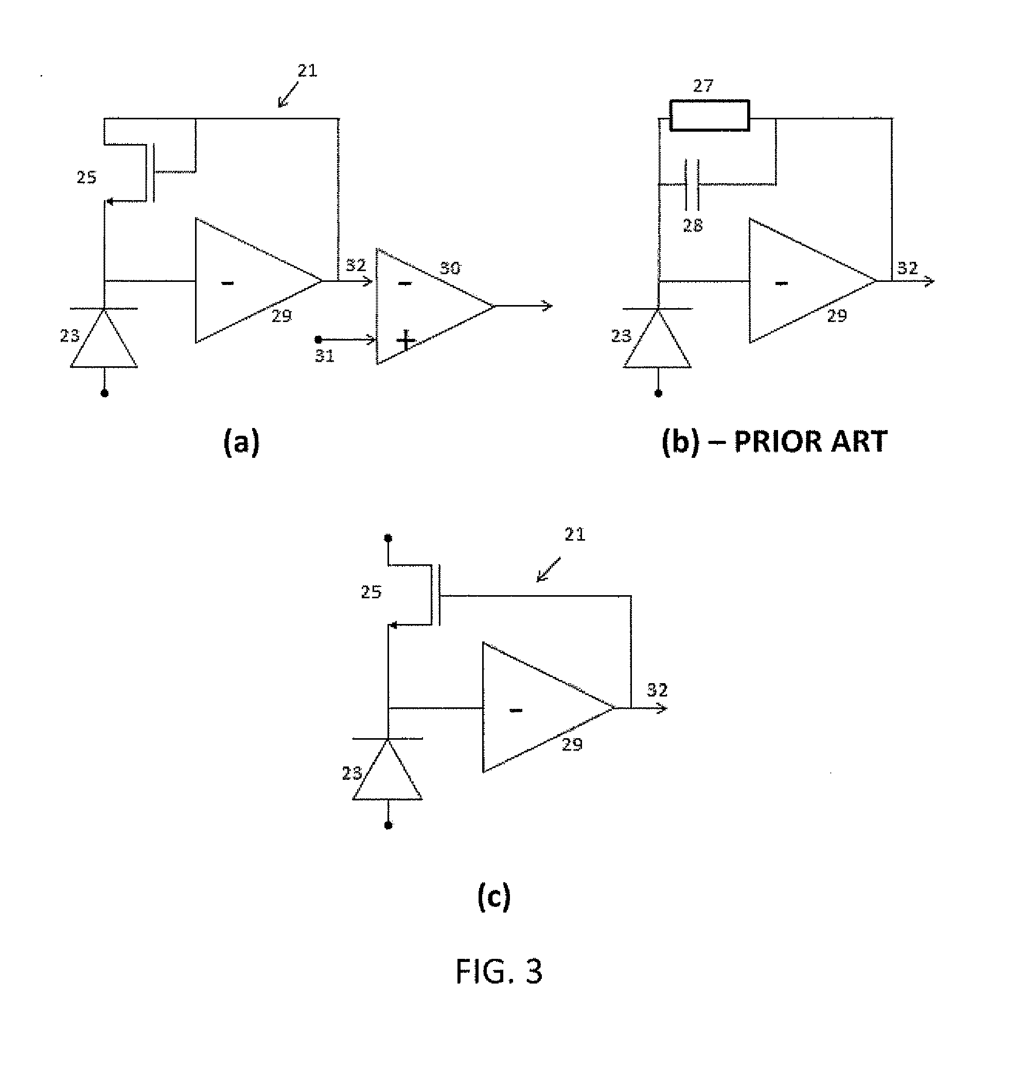
[0071]Such pulse detection circuit may typically be performed in a so-called pulse shaper circuit 21, which shapes packets...

second embodiment

[0082]A pixel according to the present invention is diagrammatically illustrated in FIG. 5. The signal from a radiation detector 50 passes first through an integrator 52 and then through a pulse detector 51 coupled in series. The pulse detector 51 and the integrator 52 are directly connected to one another, i.e. no switch or other circuitry is provided in between. Again, pulse detection and integration is performed substantially simultaneously, and on the same sensing signal emanating from the radiation detector 50.

third embodiment

[0083]A pixel according to the present invention is diagrammatically illustrated in FIG. 6. The signal from the radiation detector 50 or particle detector goes through a pulse detector 51 to an integrator 52, but the amount of the signal that goes to this integrator 52 is modulated (turned on or off) by a circuit (switch 53) that is driven by the pulse detector output. Hence, in the embodiment illustrated, a switch 53 is provided between the pulse detector 51 and the integrator 52. The output signal of the pulse detector 51 will be used to determine whether or not the integrator 52 will integrate the sensing signal. When the switch 53 is closed, pulse detection and integration is performed on the same sensing signal emanating from the radiation detector 50.


PUM


Abstract

A pixel for the detection of electromagnetic radiation or high energy particles or charge packets, in particular for detecting X-ray photons, comprises a radiation receptor for converting the radiation into a sensing signal, the pixel being adapted for performing both pulse detection and integration of the same sensing signal.

Description

FIELD OF THE INVENTION[0001]In its most general form, the present invention relates to image sensing, such as medical imaging, automotive imaging, machine vision, night vision, digital photography or digital camcorder imaging. The present invention relates to detection of electromagnetic radiation (such as for example X-rays or visible light), high energy particles or packets of or individual charged particles. In particular, the present invention relates to devices and methods for detection of radiation or high energy particles, such as for example X-ray detection.BACKGROUND OF THE INVENTION[0002]X-radiation (composed of X-rays) is a form of electromagnetic radiation. X-rays have a wavelength in the range of 10 to 0.01 nm, corresponding to frequencies in the range 30×1015 Hz to 30×1018 Hz, and energies in the range 120 eV to 120 keV. X-rays are used for medical radiography, crystallography, non-destructive testing, security etc. X-rays are in practice generated by an X-ray tube, in...

Claims


Application Information

Patent Timeline
IPC IPC(8): G01T1/24H01L27/146G01J1/44
CPCG01J1/44
Inventor DIERICKX, BART
Owner CAELESTE CVBA
Why Eureka
Try Eureka