Switched reluctance motor

Inactive Publication Date: 2012-12-06
SAMSUNG ELECTRO MECHANICS CO LTD
View PDF8 Cites 35 Cited by
  • Summary
  • Abstract
  • Description
  • Claims
  • Application Information

AI Technical Summary

Benefits of technology

[0014]The present invention has been made in an effort to provide a switched reluctan

Problems solved by technology

In particular, a cost of a motor using a permanent magnet is increased due to the sudden price increase of a rare earth material, such that a switched reluctance motor (hereinafter, referred to as an SR moto

Method used


Image

  • Switched reluctance motor
  • Switched reluctance motor
  • Switched reluctance motor

Examples


Embodiment Construction

[0041]The above and other objects, features and advantages of the present invention will be more clearly understood from the following detailed description taken in conjunction with the accompanying drawings. In the specification, in adding reference numerals to components throughout the drawings, it is to be noted that like reference numerals designate like components even though components are shown in different drawings. In addition, the terms “first”, “second”, “one surface”, “the other surface” and so on are used to distinguish one element from another element, and the elements are not defined by the above terms. In describing the present invention, a detailed description of related known functions or configurations will be omitted so as not to obscure the gist of the present invention.

[0042]Hereinafter, preferred embodiments of the present invention will be described in detail with reference to the accompanying drawings.

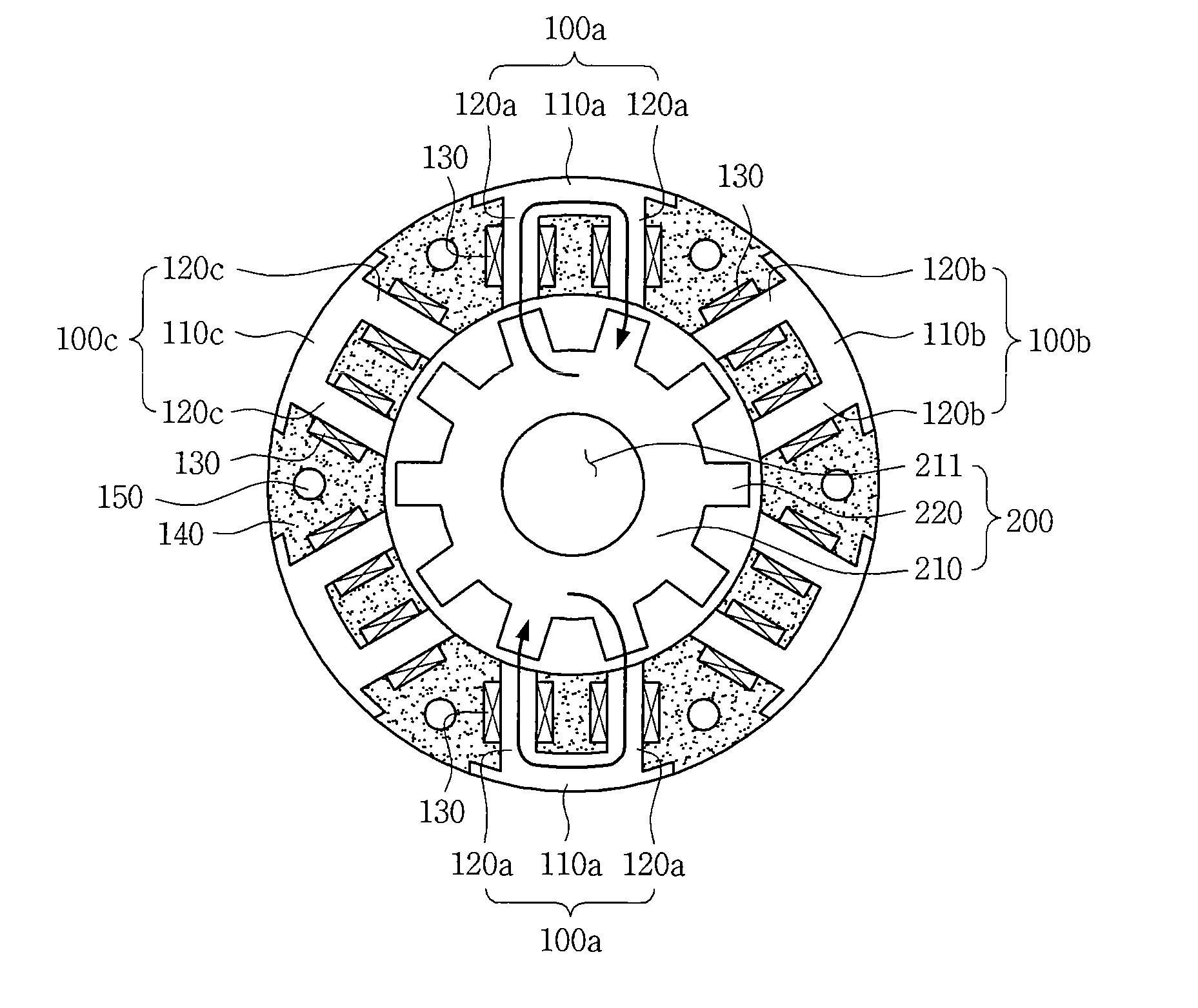
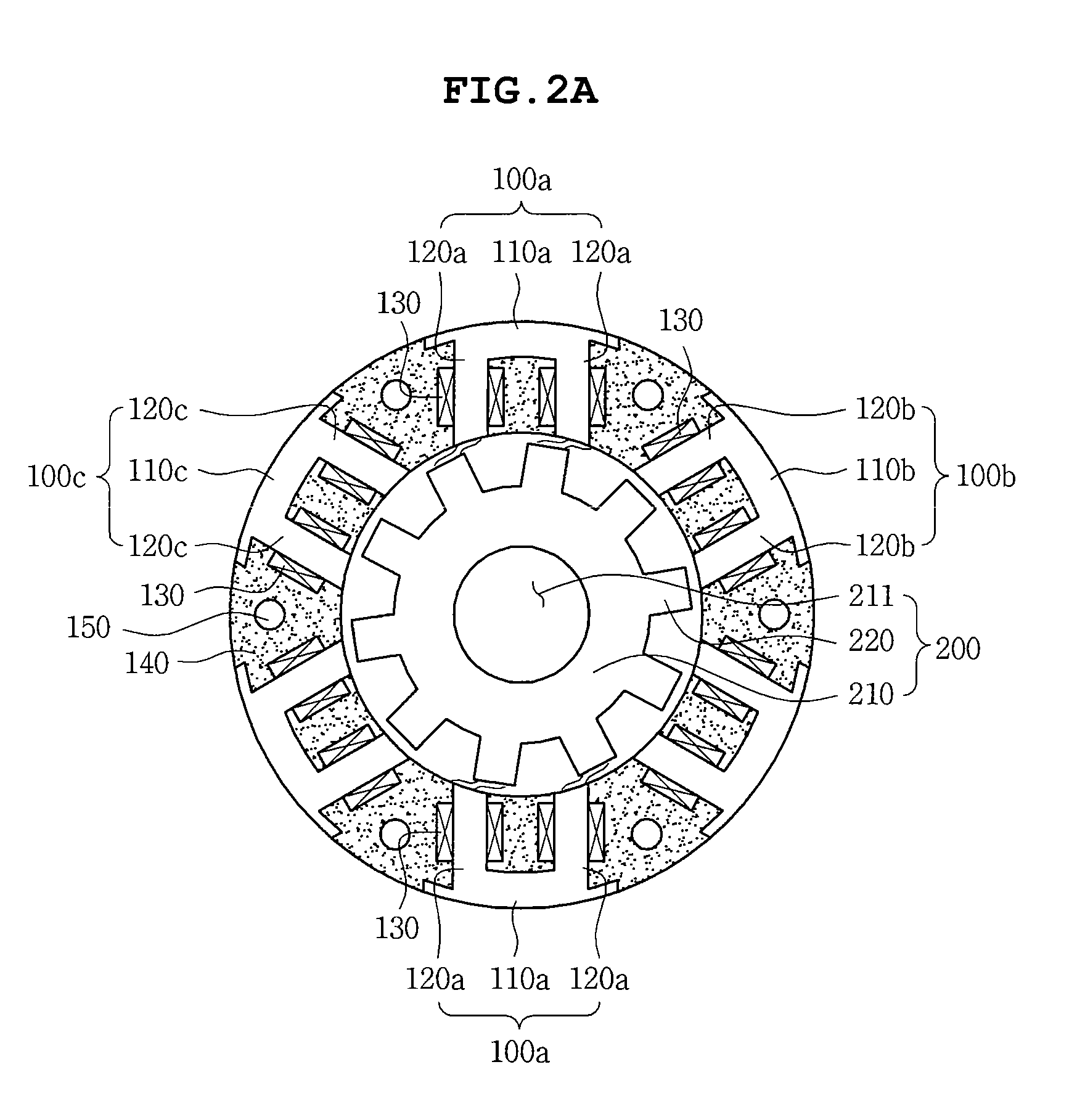
[0043]FIGS. 2A and 2B are cross-sectional views schematic...


PUM


Abstract

Disclosed herein is a switched reluctance motor, including: a rotor provided with a plurality of salient poles protruded along an outer peripheral surface thereof; and a stator including a plurality of stator cores in a pi (π) shape that have the rotor rotatably accommodated therein, are opposite to the plurality of salient poles, and have coils wound therearound, wherein a magnetic flux path is formed along the stator cores in the pi shape and the salient pole opposite thereto.

Description

CROSS REFERENCE TO RELATED APPLICATION[0001]This application claims the benefit of Korean Patent Application No. 10-2011-0053434, filed on Jun. 2, 2011, entitled “Switched Reluctance Motor” which is hereby incorporated by reference in its entirety into this application.BACKGROUND OF THE INVENTION[0002]1. Technical Field[0003]The present invention relates to a switched reluctance motor.[0004]2. Description of the Prior Art[0005]Recently, a demand for a motor has largely increased in various industries such as vehicles, aerospace, military, medical equipment, or the like. In particular, a cost of a motor using a permanent magnet is increased due to the sudden price increase of a rare earth material, such that a switched reluctance motor (hereinafter, referred to as an SR motor) has become interested as a new alternative.[0006]A driving principle of an SR motor rotates a rotor using a reluctance torque generated according to the change in magnetic reluctance.[0007]Generally, the switch...

Claims


Application Information

Patent Timeline
IPC IPC(8): H02K37/04H02K1/18
CPCH02K19/103H02K1/141H02K37/02H02K1/14H02K9/22H02K9/223
Inventor KIM, CHANGSUNG SEANCHOI, CHANG HWANBAE, HAN KYUNGLEE, GUEN HONG
Owner SAMSUNG ELECTRO MECHANICS CO LTD
Why Eureka
Try Eureka