Modified Wet Tip Antenna Design

Active Publication Date: 2012-12-06
TYCO HEALTHCARE GRP LP
View PDF4 Cites 46 Cited by
  • Summary
  • Abstract
  • Description
  • Claims
  • Application Information

AI Technical Summary

Benefits of technology

[0013]The adequate rigidity necessary for unaided direct insertion of the antenna assembly into tissue, e.g., percutaneously, while maintaining a minimal wall thickness of less than 0.010 inches of an outer jacket, comes in part by a variety of different designs. An embodiment of a microwave design includes a coaxial cable. The coaxial cable includes an inner conductor, an outer conductor, and a dielectric insulator disposed therebetween. The radi

Problems solved by technology

However, at slightly elevated temperatures above the approximate range of 43° C. to 45° C., thermal damage to most types of normal cells is routinely observed; accordingly, great care must be taken not to exceed these temperatures in healthy tissue.
There are several challenges to providing cooling to a microwave energy delivery device.
The first challenge is providing suitable supply and return flu

Method used


Image

  • Modified Wet Tip Antenna Design
  • Modified Wet Tip Antenna Design
  • Modified Wet Tip Antenna Design

Examples


Embodiment Construction

[0032]Particular embodiments of the present disclosure are described herein below with reference to the accompanying drawings. In the following description, well-known functions or constructions are not described in detail to avoid obscuring the present disclosure in unnecessary detail.

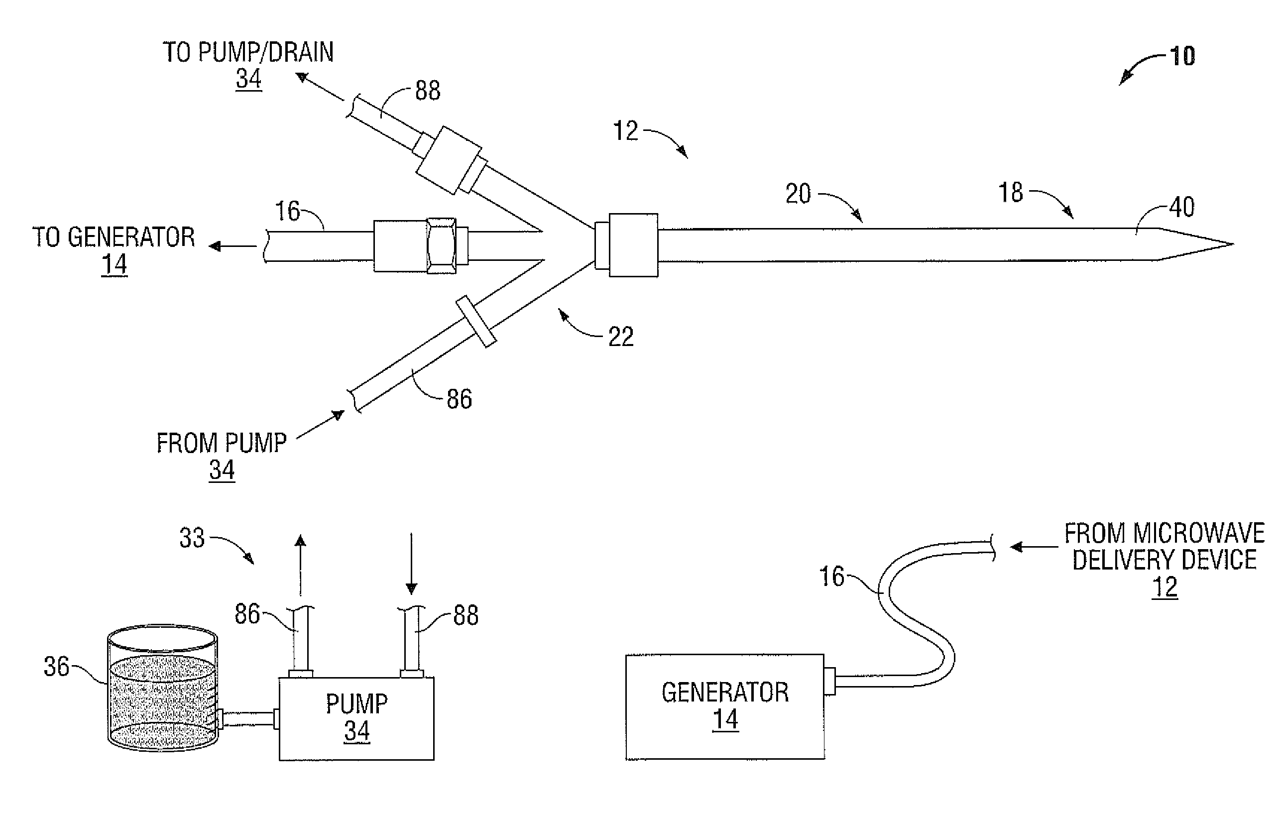
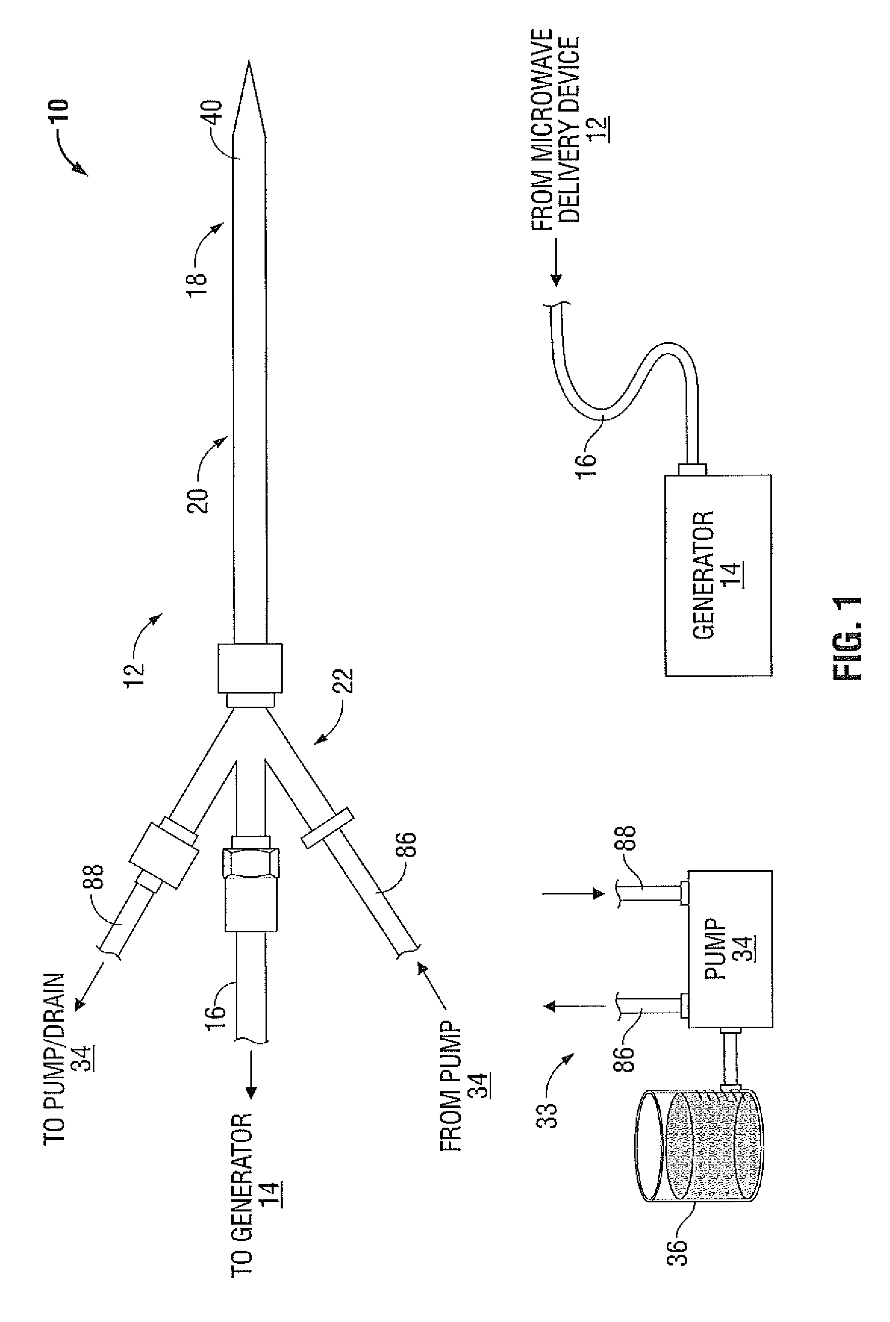
[0033]FIG. 1 illustrates a microwave ablation system 10 that includes a microwave energy delivery device 12, a microwave generator 14 and a cooling fluid supply 33. The microwave energy delivery device 12 is coupled to a microwave generator 14 via a flexible coaxial cable 16 and coupled to the cooling fluid supply 33 via cooling fluid supply lines 86 and 88. Cooling fluid exits the microwave energy delivery device 12 through a cooling fluid return line 88 and is discharged in a suitable drain. In a closed-loop cooling fluid system the microwave energy delivery device 12 couples to the cooling fluid supply 33 via a cooling fluid return line 88 and cooling fluid is cycled through the cooling fluid suppl...


PUM

PropertyMeasurementUnit
Thicknessaaaaaaaaaa

Abstract

A microwave antenna including a feedline, a radiating section, an inflow hypotube, a puck, a transition collar and a sleeve. The feedline includes a coaxial cable including an inner and outer conductor, and a dielectric disposed therebetween. The radiating section includes a dipole antenna coupled to the feedline and a trocar coupled to the distal end of the dipole antenna. The inflow hypotube is disposed around the outer conductor and configured to supply fluid to the radiating portion. The puck includes at least two ribs with inflow slots defined between two adjacent ribs. The transition collar is coupled to the distal end of the inflow hypotube and the first end of the puck. The transition collar includes at least two outflow slots configured to receive fluid from a distal end of the inflow hypotube and to transition the fluid from the outflow slots to a distal end of the radiating section. The sleeve overlays the two outflow slots of the transition collar, the puck and at least the distal portion of the radiating section. The sleeve forms a fluid-tight seal with the transition collar proximal the outflow slots and defines a first gap for transitioning the fluid to exit the outflow slots of the transition collar to the distal end of the radiating section.

Description

BACKGROUND[0001]1. Technical Field[0002]The present disclosure relates generally to microwave applicators used in tissue ablation procedures. More particularly, the present disclosure is directed to a modified version of a choked wet-tip ablation antenna.[0003]2. Background of Related Art[0004]Treatment of certain diseases requires destruction of malignant tissue growths (e.g., tumors). It is known that tumor cells denature at elevated temperatures that are slightly lower than temperatures injurious to surrounding healthy cells. Therefore, known treatment methods, such as hyperthermia therapy, heat tumor cells to temperatures above 41° C., while maintaining adjacent healthy cells at lower temperatures to avoid irreversible cell damage. Such methods involve applying electromagnetic radiation to heat tissue and include ablation and coagulation of tissue. In particular, microwave energy is used to coagulate and / or ablate tissue to denature or kill the cancerous cells.[0005]Microwave en...

Claims


Application Information

Patent Timeline
IPC IPC(8): A61B18/18
CPCA61B18/1815A61B2018/00023A61B2018/00577A61B2018/1869A61B2018/1892A61B2018/1838A61B2018/00011A61B2018/00589A61B2018/1823Y10T29/49018A61B2017/00526
Inventor BONN, KENLYN S.PETERSON, DARION R.BRANNAN, JOSEPH D.
Owner TYCO HEALTHCARE GRP LP
Why Eureka
Try Eureka