Electronically controlled focusing ophthalmic device

a technology of ophthalmology and electric control, which is applied in the field of electric control focusing ophthalmology, can solve the problems of high power consumption, limited power consumption of automatic focusing lenses, and limited power consumption of automatic focusing lenses, and achieve the effect of keeping power consumption low

Active Publication Date: 2012-12-06
INVENIOS FRANCE SAS
View PDF0 Cites 45 Cited by
  • Summary
  • Abstract
  • Description
  • Claims
  • Application Information

AI Technical Summary

Benefits of technology

[0021]Taking advantage of a microsaccade or eyelid closing event to reverse the polarization enables to make an eventual discontinuity in the electrowetting effect while reversing the polarization invisible for the patient (user).
[0022]According to a preferred embodiment, the method further comprises measuring the elapsed time since the last polarization reversal of the voltage and reversing the polarization of the DC voltage only when said elapsed time is larger than a given first value. The measurement of the elapsed time since the last polarization reversal enables to make it sure that the polarization reversal won't be made to often, thus keeping the power consumption low.

Problems solved by technology

One difficulty for automatic focusing lenses (especially for the contact lenses and for the intraocular implants) is to provide the control signal to the lens comprising the distance information on the object that the patient is looking at.
Another difficulty for an automatic focusing lens is to provide a suitable small battery or any other power source that allows the lens to be operated.
Due to the limited space available on contact lenses or intraocular implants, the available power consumption of the automatic focusing lens will be limited to very small power consumption, typically in the order of a few microwatts.
For eyeglasses, the limit of weight of the glasses also brings a constraint on the battery type, which results in the same goal of achieving an automatic focusing lens consuming no more than a few microwatts or even tens of nanowatts.
But the power consumption is high (typically a few tens of mW).
However, the dioptric correction may not be stable with time, as explained below.
This perturbation can be annoying or even unbearable.

Method used


Image

  • Electronically controlled focusing ophthalmic device
  • Electronically controlled focusing ophthalmic device
  • Electronically controlled focusing ophthalmic device

Examples


Embodiment Construction

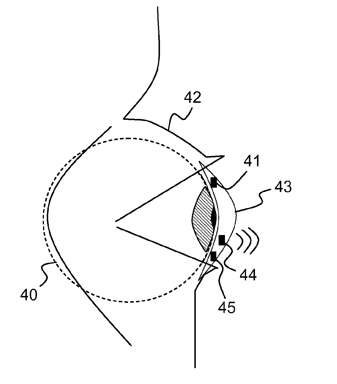
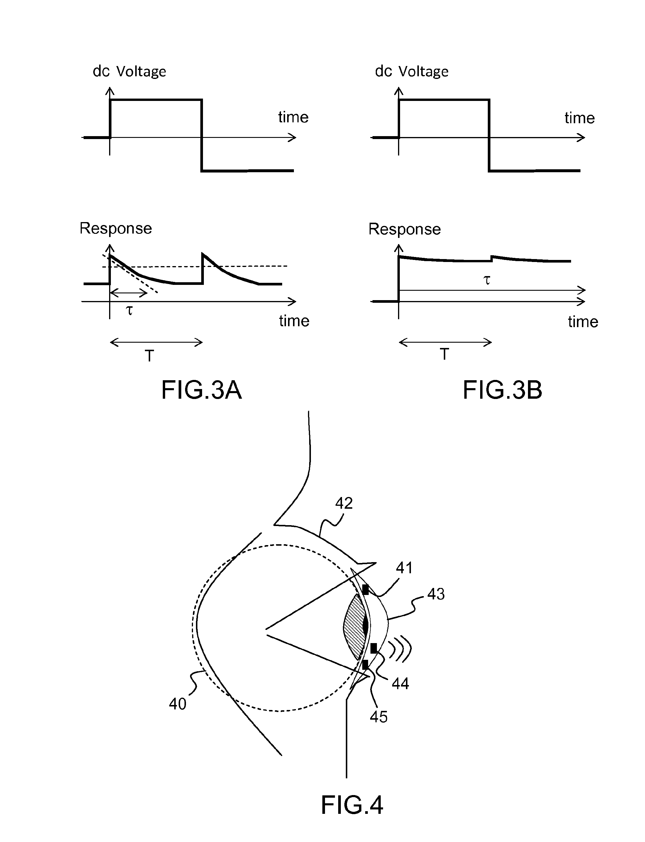
[0050]FIG. 4 shows an example of an electrically controlled focusing ophthalmic device according to a first preferred embodiment. The device comprises an active contact lens 43 to be placed on the eye 40 of a patient and comprising a liquid / liquid interface (not shown on FIG. 4) actuated by electrowetting, thus forming an active liquid lens. It further comprises a distance measuring device 44 for measuring the distance of an object to be focused on. For example, the range meter is a sensor enabling the measurement of the eye convergence of the user as described in the prior art. The device also comprises an electronic module 45 with a power supply, a driver for the liquid lens and a controller. The driver is adapted to apply to the liquid lens a voltage dependent on the desired focusing. The desired focusing may be calculated from the distance of an object measured by the distance measuring device 44, thus making an automatic focusing of the device. Reversal of the polarization of t...


PUM


Abstract

According to a first aspect, the invention relates to an electrically controlled focusing ophthalmic device (43) to be worn by a user, comprising:—at least one active liquid lens comprising a liquid/liquid interface movable by electrowetting under the application of a voltage,—a driver for applying a DC voltage to said active liquid lens, the amplitude of the voltage to be applied being a function of the desired focusing;—a sensor (41) for detecting eyelid closing events and/or microsaccades of the user;—a controller for synchronizing said sensor and the driver, such that the driver may reverse the polarization of the DC voltage during a microsaccade and/or an eyelid closing event of the user.

Description

BACKGROUND[0001]1. Field of the Disclosure[0002]The invention relates to an electronically controlled focusing ophthalmic device, and more particularly to an automatic focusing ophthalmic device for the treatment of accommodation disorders, such as presbyopia. Such ophthalmic devices are for example eyeglasses, contact lenses or intra ocular implants.[0003]2. Background Art[0004]Presbyopia is a condition where the eye exhibits a progressively diminished ability to focus on near objects with age. Another situation where people are loosing accomodation is after a cataract surgery; following surgical removal of the natural lens, an artificial intraocular lens implant is inserted, which is a fixed focal lens made of a transparent polymer. Corrective lenses and contact lenses have been largely developed to correct the focusing loss that comes along with presbyopia and other accomodation disorders. More recently, implantation of accommodative intraocular lenses (IOLs) has been developed.[...

Claims


Application Information

Patent Timeline
Patent Type & Authority Applications(United States)
IPC IPC(8): A61F2/16
CPCG02C7/085G02B3/14A61B3/10
Inventor BERGE, BRUNO
Owner INVENIOS FRANCE SAS
Why Eureka
Try Eureka