Keyless entry device for vehicle

a keyless entry and vehicle technology, applied in anti-theft devices, process and machine control, instruments, etc., can solve the problems of high probability of overlap between a plurality of vehicles, method induces an unexpected failure in some cases, and the operation of a system is likely to become unstable, so as to improve the reliability of the system, improve the practical convenience, and the general versatility is high.

a keyless entry and vehicle technology, applied in anti-theft devices, process and machine control, instruments, etc., can solve the problems of high probability of overlap between a plurality of vehicles, method induces an unexpected failure in some cases, and the operation of a system is likely to become unstable, so as to improve the reliability of the system, improve the practical convenience, and the general versatility is high.

US20120310447A1Inactive Publication Date: 2012-12-06ALPS ALPINE CO LTD

Image

  • Keyless entry device for vehicle
  • Keyless entry device for vehicle
  • Keyless entry device for vehicle

Examples


Embodiment Construction

[0044]Hereinafter, embodiments of the present disclosure will be described with reference to drawings. The following description is intended to convey a thorough understanding of the embodiments described by providing a number of specific embodiments and details involving a keyless entry device for a vehicle. It should be appreciated, however, that the present invention is not limited to these specific embodiments and details, which are exemplary only. It is further understood that one possessing ordinary skill in the art, in light of known systems and methods, would appreciate the use of the invention for its intended purposes and benefits in any number of alternative embodiments, depending on specific design and other needs.

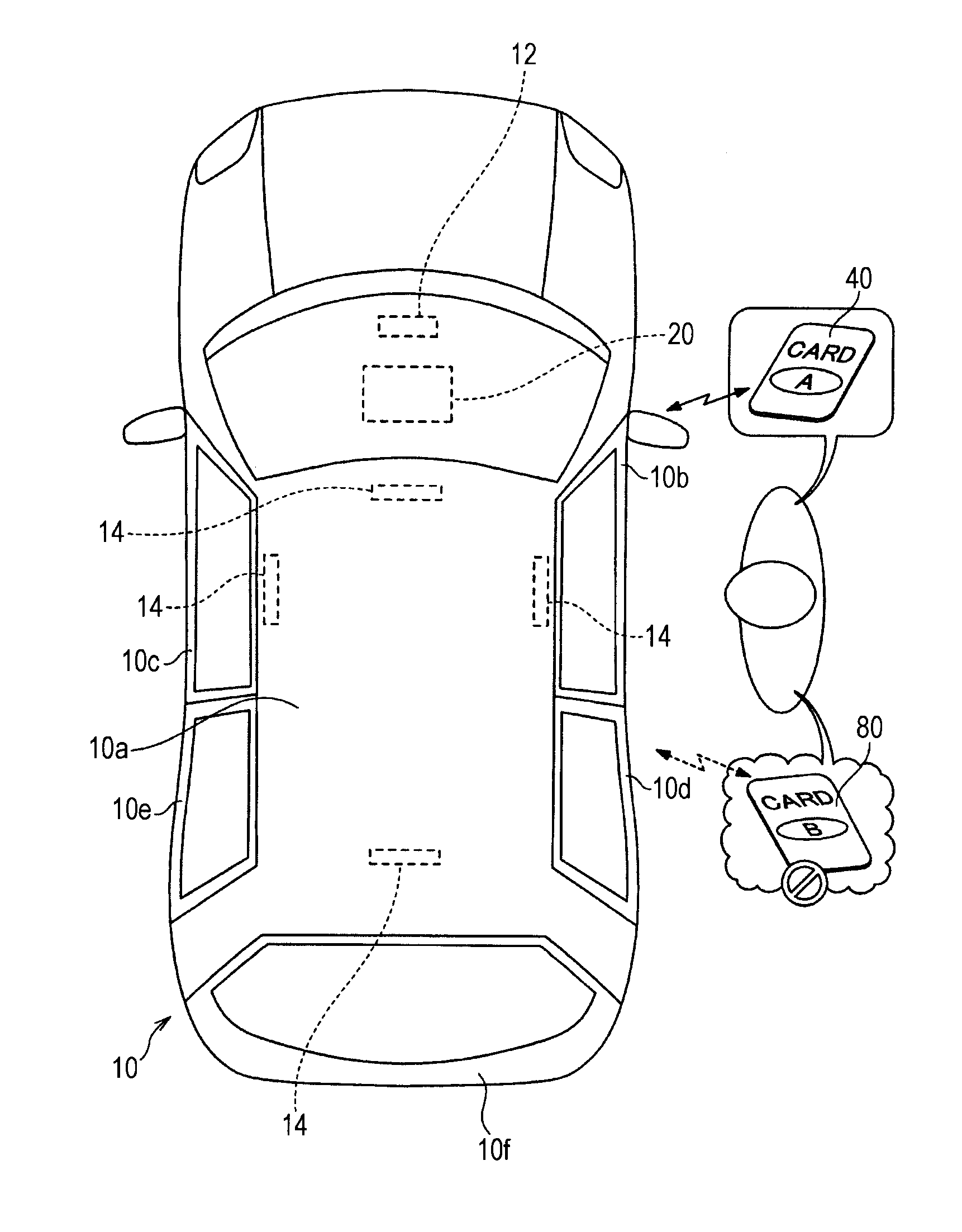
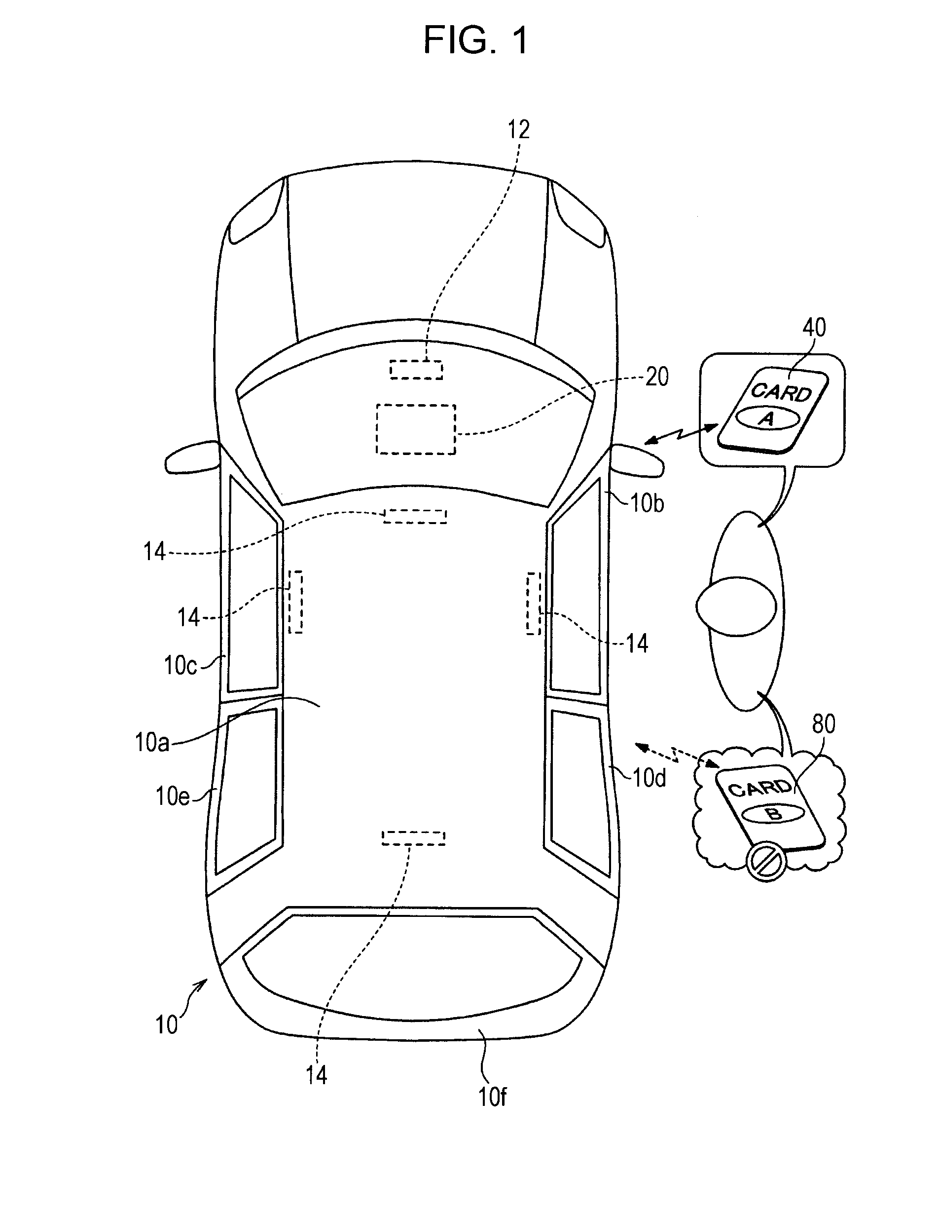
[0045]FIG. 1 is a diagram illustrating the schematic configuration of a keyless entry device of an embodiment. For example, the keyless entry device may be built into a van-type vehicle 10, or any vehicle, and, include a reception antenna 12, a plurality of tra...


PUM


Abstract

First, “Sync+Wakeup ID” is transmitted form a first vehicle (from a first time to a second time). While a first portable device paired with the first vehicle does not respond to this, when another second portable device has an inverted code coinciding by chance, the second portable device transmits a “Welcome” response (from the second time to a fifth time). During this response, a “Who” command including proper “Sync+Wakeup ID” and “command+additional data” is transmitted, thereby allowing the first portable device to normally respond to “Who” (a sixth time).

Description

CLAIM OF PRIORITY[0001]This application contains subject matter related to and claims the benefit of Japanese Patent Application No. 2011-123063 filed on Jun. 1, 2011, the entire contents which is incorporated herein by reference.BACKGROUND OF THE DISCLOSURE[0002]1. Field of the Disclosure[0003]The present disclosure relates to a keyless entry device for a vehicle, which performs control of causing the equipment of the vehicle to operate, under the condition that authentication based on wireless communication that has been established between an on-vehicle device and a portable device a user possesses.[0004]2. Description of the Related Art[0005]An example of on on-vehicle device remote controller known as a smart key system has been disclosed in Japanese Unexamined Patent Application Publication No. 2009-68255. This on-vehicle device remote controller regularly transmits an activation signal by wireless (a regular transmission method) from an antenna on a vehicle side to a vehicle ...

Claims


Application Information

Patent Timeline
06 Dec 2012
Publication
US20120310447A1
IPC
G06F17/00; B60R25/01; B60R25/10; B60R25/24
CPC
B60R25/24
Inventors
TOKI, IWAO