Tape attaching apparatus and tape attaching method

Inactive Publication Date: 2012-12-13
NEC ENG LTD
View PDF4 Cites 9 Cited by
  • Summary
  • Abstract
  • Description
  • Claims
  • Application Information

AI Technical Summary

Benefits of technology

[0012]As described above, according to the present invention, it is possible to reduce a load on an attachment target object and prevent breakage or damage of the attachment target object in the case of attaching a tape to an attachment target object having a low rigidity.

Problems solved by technology

However, since this method is carried out in the atmosphere, air is liable to be entrapped between the wafer 42 and the tape 43.
When dicing (chip segmentation) is performed in such a state, cracking or chipping occurs in the chip.

Method used


Image

  • Tape attaching apparatus and tape attaching method
  • Tape attaching apparatus and tape attaching method
  • Tape attaching apparatus and tape attaching method

Examples


Embodiment Construction

[0035]Next, modes for carrying out the invention will be described in detail with reference to the drawings. Herein, an example is described in which a tape attaching apparatus according to the present invention is applied to attachment of a dicing tape to a semiconductor wafer.

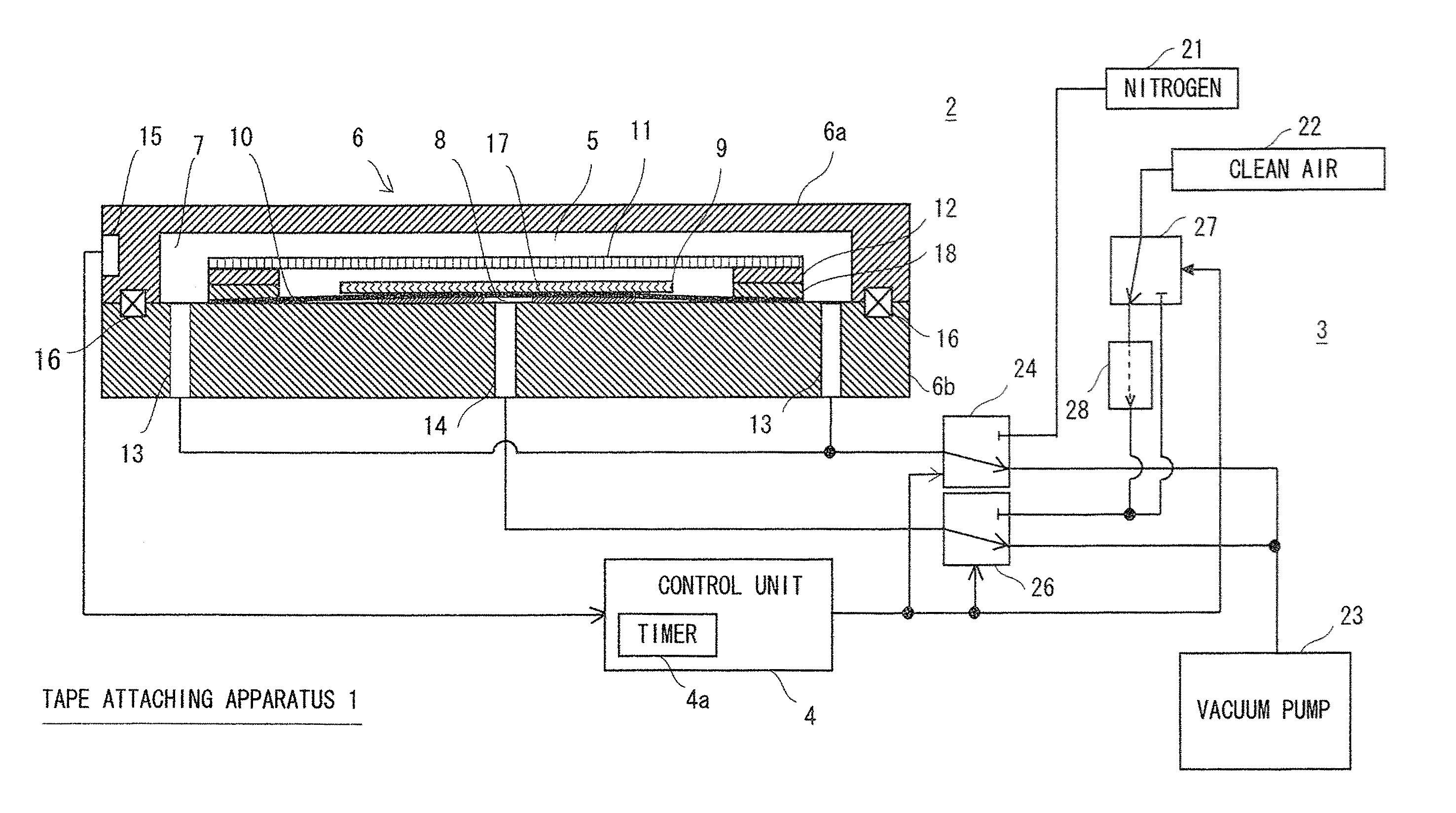
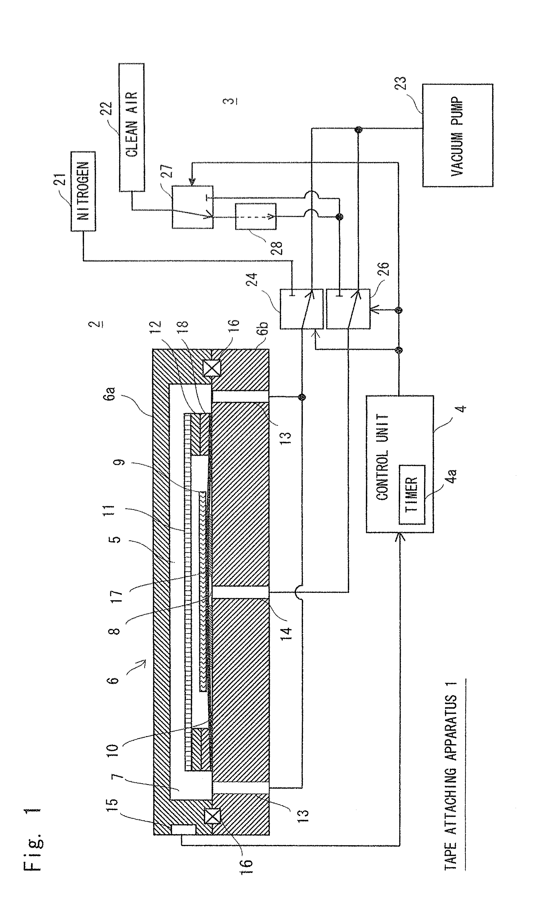
[0036]FIG. 1 shows an exemplary embodiment of the tape attaching apparatus according to the present invention. This tape attaching apparatus 1 is broadly divided into an apparatus main body 2, a supply / exhaust mechanism 3 which supplies air (clean air) and nitrogen to the apparatus main body 2 and sucks air or the like from the apparatus main body 2, and a control unit 4 which controls timings for supplying / discharging air or the like.

[0037]The apparatus main body 2 is an apparatus for performing an attachment operation. The apparatus main body 2 is formed in a cylindrical shape. This apparatus main body 2 includes a chamber (container) 6 having an airtight space 5 formed therein; a rubber sheet 10 which part...


PUM

PropertyMeasurementUnit
Speedaaaaaaaaaa

Abstract

A tape attaching apparatus includes: a chamber having an airtight space formed therein; a rubber sheet that partitions the airtight space into first and second airtight spaces and has an upper sheet on which a wafer is placed; a tape frame that holds a tape above the rubber sheet; and first and second supply / exhaust tubes that switch pressurization and depressurization of the first and second airtight spaces. In pressurizing the second airtight space and expanding the rubber sheet to lift the wafer to be attached to the tape, after bringing the first and second airtight spaces into a vacuum state, the wafer is attached to the tape while an amount of pressurization of the second airtight space is controlled to change an expansion rate of the rubber sheet from a low speed to a high speed stepwisely.

Description

TECHNICAL FIELD[0001]The present invention relates to a tape attaching apparatus and a tape attaching method for use in attaching a dicing tape to a semiconductor wafer, and more particularly, to an apparatus suitable for attaching a tape to an attachment target object having a low rigidity, for example.BACKGROUND ART[0002]In the case of attaching a dicing tape to a semiconductor wafer during a semiconductor manufacturing process, for example, as shown in FIG. 17, a wafer 42 is placed on a base 41 and a tape 43 is pressed from above to be attached by a roller 44 having rubber attached to the surface thereof, a block having a cylindrical shape, or the like. However, since this method is carried out in the atmosphere, air is liable to be entrapped between the wafer 42 and the tape 43. When dicing (chip segmentation) is performed in such a state, cracking or chipping occurs in the chip.[0003]In this regard, an attaching apparatus for attaching a tape under a vacuum environment is propo...

Claims


Application Information

Patent Timeline
IPC IPC(8): B29C65/50
CPCH01L21/67092Y10T156/17H01L21/6838H01L21/67132H01L21/30H01L21/683H01L21/6836
Inventor TAGA, YOICHIROAOKI, EIICHIRO
Owner NEC ENG LTD
Why Eureka
Try Eureka