
Arrangement for generating a control signal for controlling a power output of a power generation system

a power generation system and control signal technology, applied in the direction of electric variable regulation, process and machine control, instruments, etc., can solve the problem of frequency variation that is often observed, and achieve the effect of improving control

Active Publication Date: 2012-12-13
SIEMENS GAMESA RENEWABLE ENERGY AS
View PDF1 Cites 34 Cited by
  • Summary
  • Abstract
  • Description
  • Claims
  • Application Information

AI Technical Summary

Benefits of technology

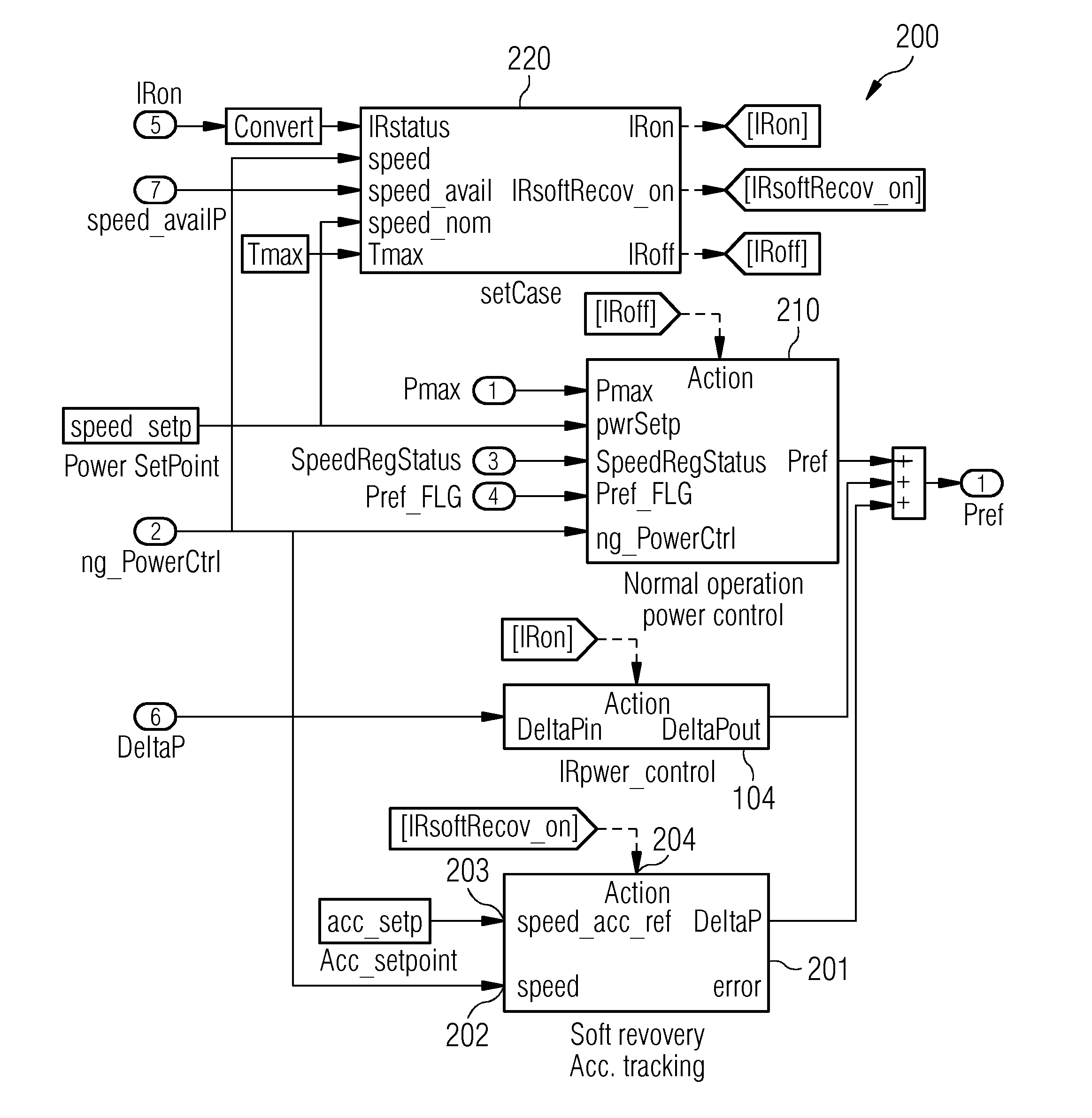
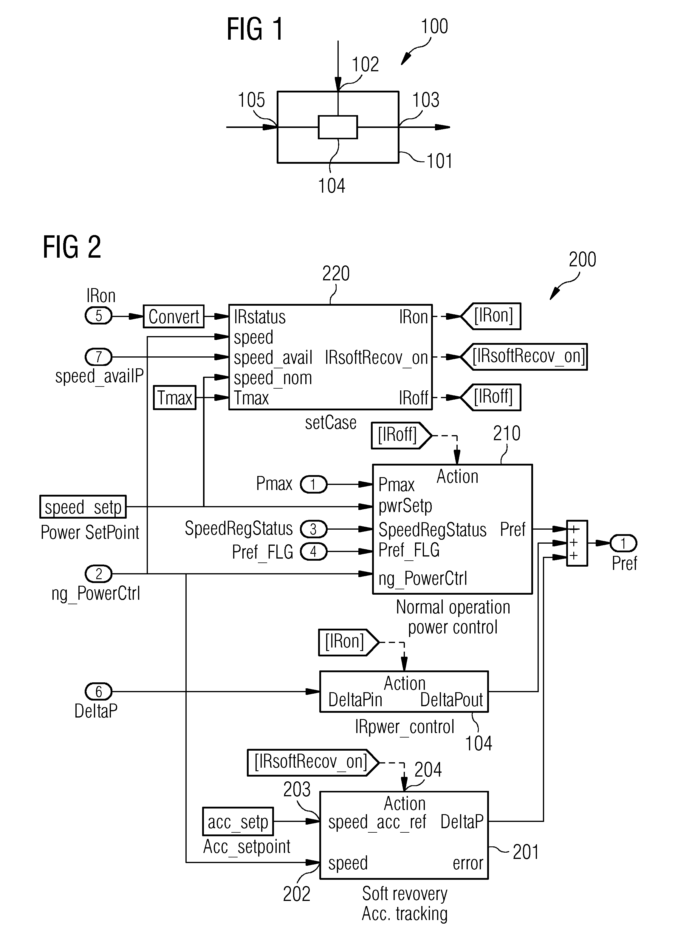
[0029]The control circuit bypasses the power control used in normal operation in order to extract additional active power from the rotational system, which is decelerated accordingly. When the inertia response is completed and normal operation is to be reactivated a double dip can occur in certain operating conditions due to different power and / or speed operation modes within the turbine control system. To avoid this unwanted consequence, the normal power control might not be reinstated until the generator speed matches that of the present or determined optimal operating condition. To achieve this, the power reference of the normal power controller may be overridden from its power and / or speed controlling scheme temporarily. During this short time period, the power reference is reduced slightly below actual power reference level (the power level where the bang-bang controller became deactivated) and a controlled acceleration of the generator is initiated by the recovery unit.
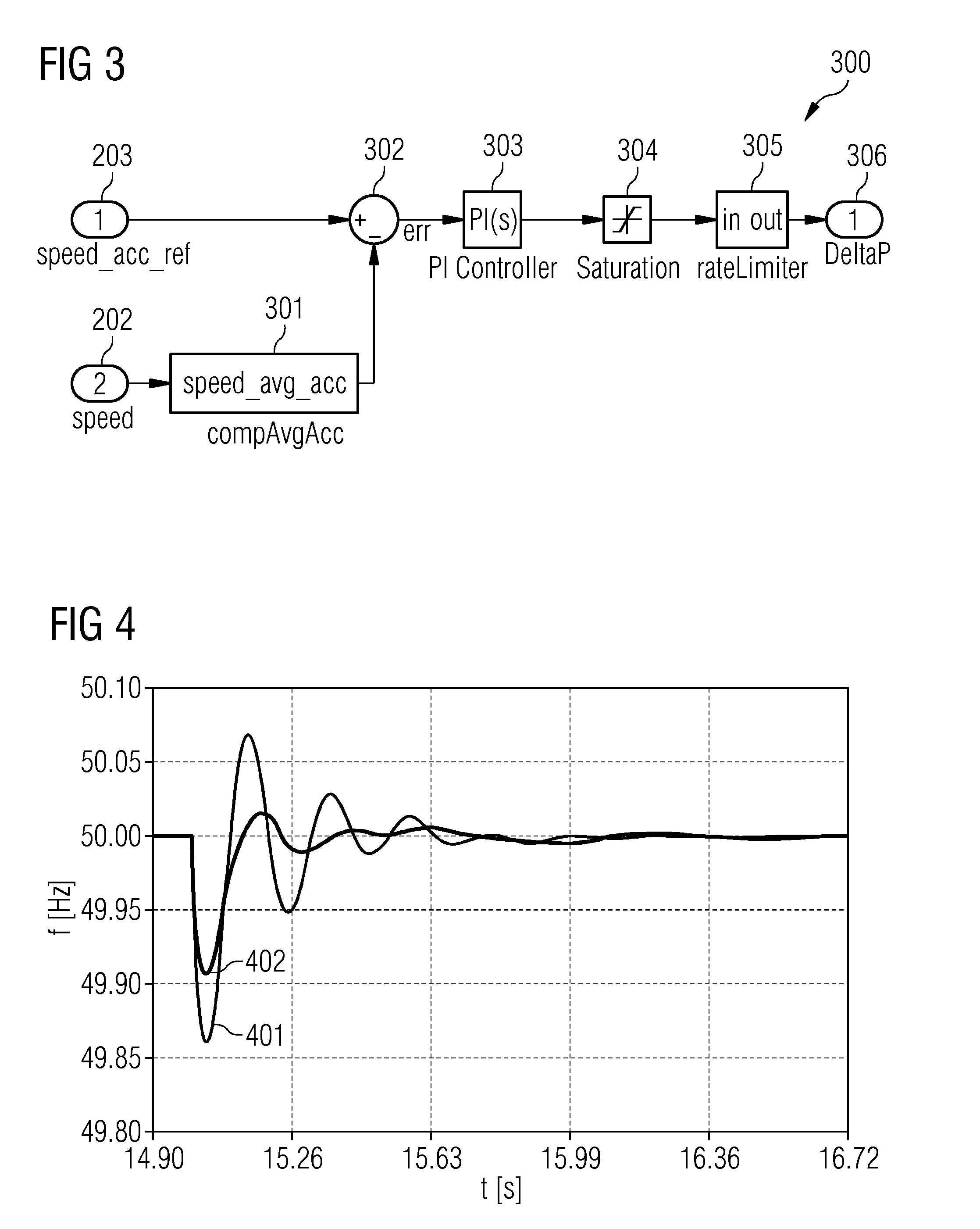
[0032]According to an embodiment, the recovery unit further comprises a limiting circuit connected between the PI controller and an output terminal of the recovery unit for limiting the control signal to be below a predetermined change per time (such that a change of the control signal within a particular time interval is below a change threshold) and / or to be in a predetermined range (a range of values of the control signal), wherein the predetermined range is 0.0 to 0.2, in particular 0.0 to 0.1, times a nominal power output (also referred to as a rated power output, i.e. a power output of the power generation system, in particular the wind turbine, for continuous operation or normal operation) of the power generation system. Thereby it may be avoided that the power generation system is operated under conditions the power generation system is not designed to operate in. Thereby, a lifetime of the power generation system may be increased.
[0034]Alternatively, the static limiting circuit may be a simple implementation how much active power the turbine is able to provide which may highly depend on the active power delivered to the grid (just before the inertial response) and the generator rotational speed.
[0038]In particular, the load determination unit may allow to estimate or measure an accumulated load the power production system or wind turbine system is subjected to. Further, the load determination unit may allow estimation or measuring of an expected lifetime of the power generation system, in particular the wind turbine. Further, the measurements or estimations of the load determination unit may be taken into account for generating the control signal. Thus, the control signal may be generated also to be based on a load determined by the load determination unit. Thereby, the control of the power generation system regarding its power output may be improved.
[0040]In particular, the control signal may be used by the converter to trigger conducting states of one or more semiconductor switches, such as IGBTs, which control the flow of power through the converter. In particular, the converter may receive a variable frequency AC power signal from the generator (which may be mechanically coupled to the rotor shaft having rotor blades fixed thereto) to a DC power signal using one or more semiconductor switches, such as isolated gate bipolar transistors (IGBTs). The DC power signal may then be converted by the converter using one or more IGBTs to a fixed frequency AC power signal having a frequency close to the fixed nominal grid frequency. Controlling the conducting states of the IGBTs comprised in the converter may allow controlling flow of power through the IGBT into the utility grid. Thereby, the frequency oscillations in the utility grid may be decreased.

Problems solved by technology

This balance of generated and consumed power is necessary to keep the frequency stable, but due to outage, generation loss and sudden increase in power a variation in frequency is often observed.

Method used


Image

  • Arrangement for generating a control signal for controlling a power output of a power generation system
  • Arrangement for generating a control signal for controlling a power output of a power generation system
  • Arrangement for generating a control signal for controlling a power output of a power generation system

Examples


Embodiment Construction

[0065]The illustration in the drawings is in schematic form. It is noted that in different figures, similar or identical elements are provided with the same reference signs.

[0066]In power generation systems, the grid frequency highly depends on the balance of generated and consumed power. This balance is necessary to keep the grid frequency stable, but due to outage, generation loss and sudden increase in power, a variation in frequency is seen. Common power plants increase production of active power when the frequency falls below a certain limit, and conversely reduce the power production when having over frequency event.

[0067]Common power plants are to be replaced by large scale wind farms within the coming decades which sets new requirement for the operation and control of wind power plants (WPP). Wind turbines (WT) with a full-scale converter have effectively decoupled the rotor side from the grid dynamics This decoupling results in that the grid does not have a direct link to t...


PUM


Abstract

An arrangement for generating a control signal for controlling a power output of a power generation system, such as a wind turbine, is provided. The power output is supplied to a utility grid. The arrangement includes a first input terminal for receiving a first input signal indicative of an actual grid frequency of the utility grid, a control circuit for generating the control signal, and an output terminal to which the control signal is supplied. The control circuit includes a bang-bang controller for generating a first power signal being indicative of a predefined amount of power to be added to the power output of the power generation system. The bang-bang controller is adapted to be activated when the first input signal falls below a first predefined threshold. The control signal depends on the first power signal.

Description

CROSS REFERENCE TO RELATED APPLICATIONS[0001]This application claims priority of European Patent Office application No. 11169135.8 EP filed Jun. 8, 2011. All of the applications are incorporated by reference herein in their entirety.FIELD OF INVENTION[0002]The present invention relates to an arrangement for generating a control signal for controlling a power output of a power generation system and to a power generation system including the arrangement. In particular, the present invention relates to an arrangement for generating a control signal for controlling a power output of a power generation system and to a power generation system, which is adapted to stabilize oscillations of a frequency of a utility grid to which the power generation system is supposed to supply electric energy.BACKGROUND OF INVENTION[0003]One or more power generation systems, such as wind turbines, may be connected to a utility grid to supply electric energy to the utility grid. On the other hand, one or mo...

Claims


Application Information

Patent Timeline
Patent Type & Authority Applications(United States)
IPC IPC(8): G05F1/10
CPCY02E10/723Y02E10/725Y02E10/763F05B2270/70F03D7/0284F05B2270/337H02J3/386H02J2300/28H02J3/381Y02E10/72Y02E10/76H02J3/48
Inventor KNUPPEL, THYGEKUMAR, SATHEESTHURING, PATRIK
Owner SIEMENS GAMESA RENEWABLE ENERGY AS
Learn More