Method of locating valid light spots for optical measurement and optical measurement instrument employing method of locating valid light spots

a technology of optical measurement and light spot location, which is applied in the field of optical measurement and optical measurement instruments employing the method of locating valid light spots, can solve the problems of reducing the accuracy of traditional light spot location algorithms, affecting the resultant wavefront measurement, and reducing the breakup effect of tear film

Active Publication Date: 2012-12-13
AMO DEVMENT
View PDF2 Cites 7 Cited by
  • Summary
  • Abstract
  • Description
  • Claims
  • Application Information

AI Technical Summary

Benefits of technology

[0028]Another source of error in wavefront measurements is tear film breakup. Tear film break up can affect the location and sharpness of the light spots in the vicinity of the breakup. Tear film breakup is correlated to delays in blinking the eye. Some measurement systems may be designed to operate rapidly and reduce tear film breakup effects by avoiding the need to keep the patient from blinking for long periods. Nevertheless, it is still possible that light spots are affected by tear film breakup. This can negatively impact the resultant wavefront measurements.

Problems solved by technology

In particular, if the wavefront is not isoplanatic, the quality of the light spots erodes rapidly and it becomes more difficult to determine the locations of the light spots.
This will lead to errors in these traditional light spot location algorithms.
In addition to the problem of determining the locations of light spots for a highly aberrated light beam, in some cases lenslet array 110 may not be perfectly aligned with the pixels of detector array 120.
Additionally, there is a problem of determining what constitutes a valid light spot on the detector array.
For these reasons, the qualification and / or exclusion of light spot data in and around the corneal reflex can be challenging.
This leads to variability in the relative brightness of the focal spots.
Such focal spot distributions can lead to inaccurate identification of the light spot location and therefore inaccurate wavefront measurements.
Another source of error in wavefront measurements is tear film breakup.
Nevertheless, it is still possible that light spots are affected by tear film breakup.
This can negatively impact the resultant wavefront measurements.
It is apparent that the light spot location information is compromised when the spot brightness is poor compared to stray light and camera noise.

Method used


Image

  • Method of locating valid light spots for optical measurement and optical measurement instrument employing method of locating valid light spots
  • Method of locating valid light spots for optical measurement and optical measurement instrument employing method of locating valid light spots
  • Method of locating valid light spots for optical measurement and optical measurement instrument employing method of locating valid light spots

Examples


Embodiment Construction

[0045]Methods and systems for locating valid light spot data as described below can be employed in a variety of different measurement instruments. Exemplary embodiments will be described in some detail below so as to illustrate various aspects and advantages of these methods. However, it should be understood that the principles involved in these method can be employed in a variety of other measurement instruments which employ light spot data.

[0046]FIG. 4 illustrates one embodiment of a measurement instrument employing a wavefront sensor. In particular, FIG. 4 illustrates a wavefront aberrometer 400 for making wavefront measurements of a subject's eye 10. Among other components, wavefront aberrometer 400 includes a light source 410, a wavefront sensor 420, and other components on a moving stage 430, a processor 440, memory 450 associated with the processor 440, and an iris camera 460. Further details of the construction and operation of wavefront aberrometer 400 can be found in U.S. ...


PUM


Abstract

An algorithm locates valid light spots produced on an image detector by a wavefront of interest. The algorithm includes sequentially examining pixels of the image detector to determine for each of the pixels whether the light intensity detected by the pixel is greater than a threshold, When the pixel's detected light intensity is determined to be greater than the threshold, the algorithm includes: determining whether the pixel belongs to a valid light spot; and when the pixel is determined to belong to a valid light spot; saving data indicating a location for the valid light spot; and masking out a group of pixels of the image detector at the determined location such that the masked pixels are considered to have a light intensity less than the threshold for a remainder of the sequential examination.

Description

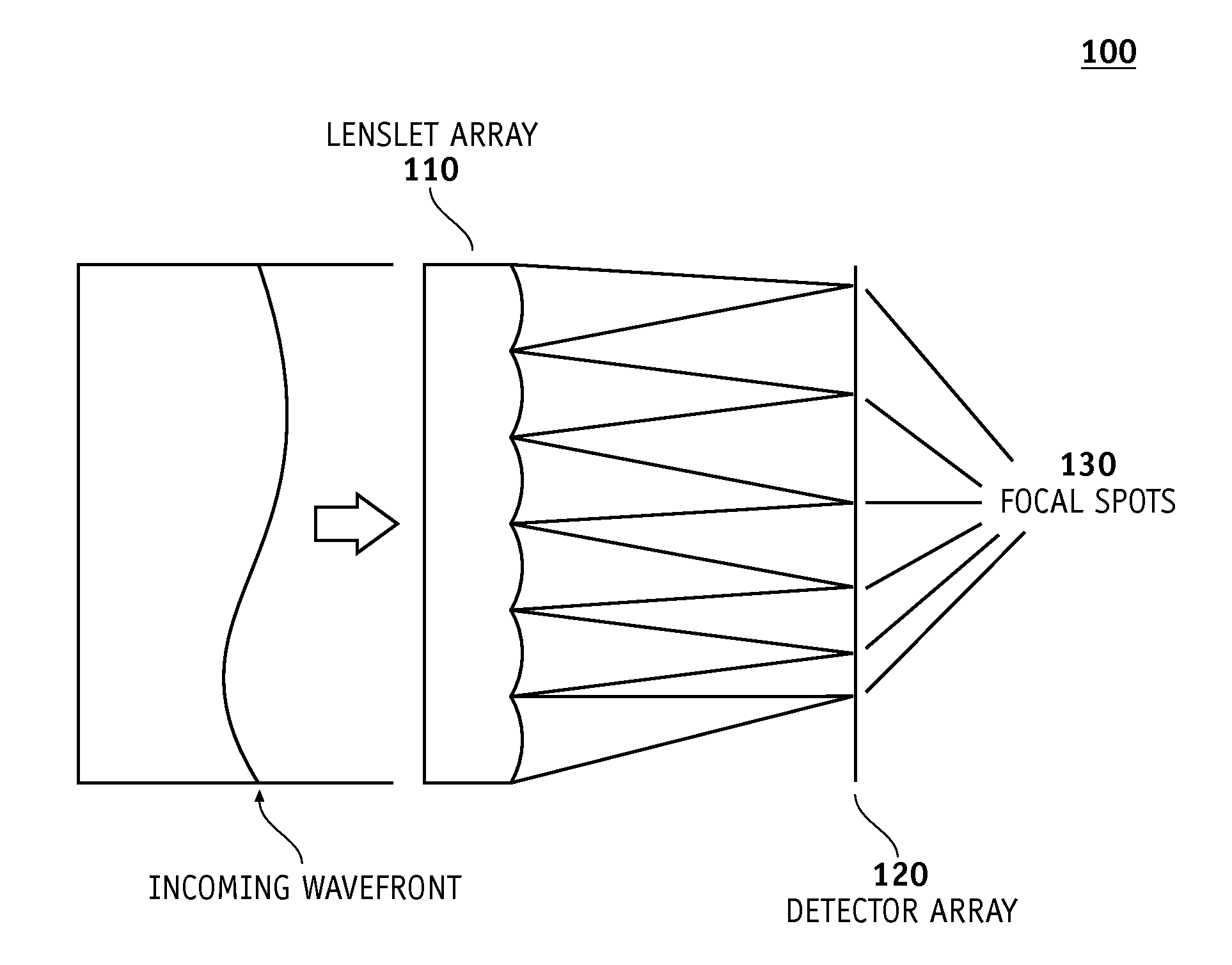
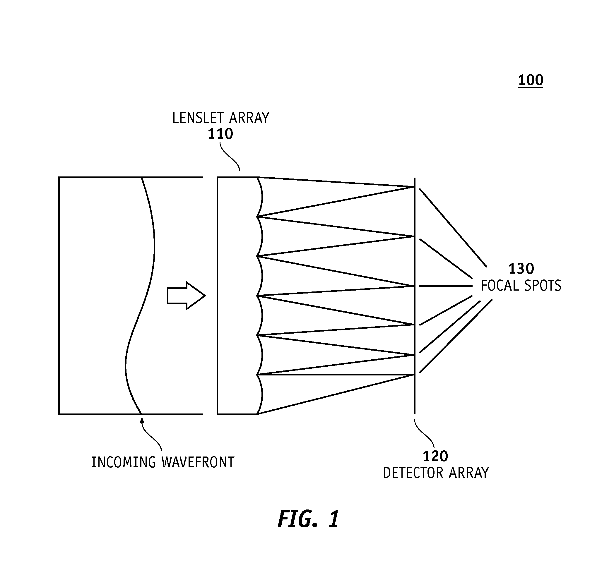
BACKGROUND AND SUMMARY[0001]1. Field[0002]This invention pertains to devices and methods for performing optical measurements using a plurality of light spots, and more particularly, to a method of locating valid light spots for use in making optical measurements by a measurement instrument, and a measurement instrument employing such a method of locating the valid light spots that are employed in its measurements.[0003]2. Description[0004]There are some instruments which employ light spots to make optical measurements. Well-known examples include instruments which employ a Shack-Hartmann wave front sensor.[0005]FIG. 1 illustrates some principal elements of a basic configuration of a Shack-Hartmann wavefront sensor 100. Shack-Hartmann wavefront sensor 100 comprises a micro-optic lenslet array 110 and an optical detector 120. Typically, the optical detector 120 comprises a detector array or pixel array, for example, a charge-coupled device (CCD) camera or CMOS array.[0006]The lenslets...

Claims


Application Information

Patent Timeline
Patent Type & Authority Applications(United States)
IPC IPC(8): A61B3/10A61B3/00
CPCA61B3/1015G01J1/4228
Inventor FARRER, STEPHAN W.RAYMOND, THOMAS D.XIONG, WEIDIXSON, JOHNNEAL, DANIEL R.
Owner AMO DEVMENT
Why Eureka
Try Eureka