Powerline Control Interface for Frequency and Amplitude Modulation Transmitter

a powerline control and frequency modulation technology, applied in power distribution line transmission, powerline communications applications, digital transmission, etc., can solve the problems of limited use of plc technology, limited integration of line couplers into systems on chips, and system power consumption up to a few watts in some cases, so as to reduce the overall supply power needed

Inactive Publication Date: 2012-12-13
BOIVIN DIDIER +1
View PDF5 Cites 8 Cited by
  • Summary
  • Abstract
  • Description
  • Claims
  • Application Information

AI Technical Summary

Benefits of technology

[0024]Further embodiment is to apply a voltage (V+) during the transmission and to use some electronics to produce a threshold voltage allowing a Linear Amplifier to commute and then transmit the modulation signal to the Transistor (i.e: MOS FET) b

Problems solved by technology

Typically traditional PLC systems are injecting (“pushing”) data transmit power into the power line, which drives the power consumption of the system up to a few watts in some cases.
As a result,

Method used


Image

  • Powerline Control Interface for Frequency and Amplitude Modulation Transmitter
  • Powerline Control Interface for Frequency and Amplitude Modulation Transmitter
  • Powerline Control Interface for Frequency and Amplitude Modulation Transmitter

Examples


Embodiment Construction

[0041]The present invention will be better understood and fully appreciated when read in conjunction with the appended drawings. It should be understood, however, that the present invention is not limited to the precise arrangements and instrumentations as shown in the drawings.

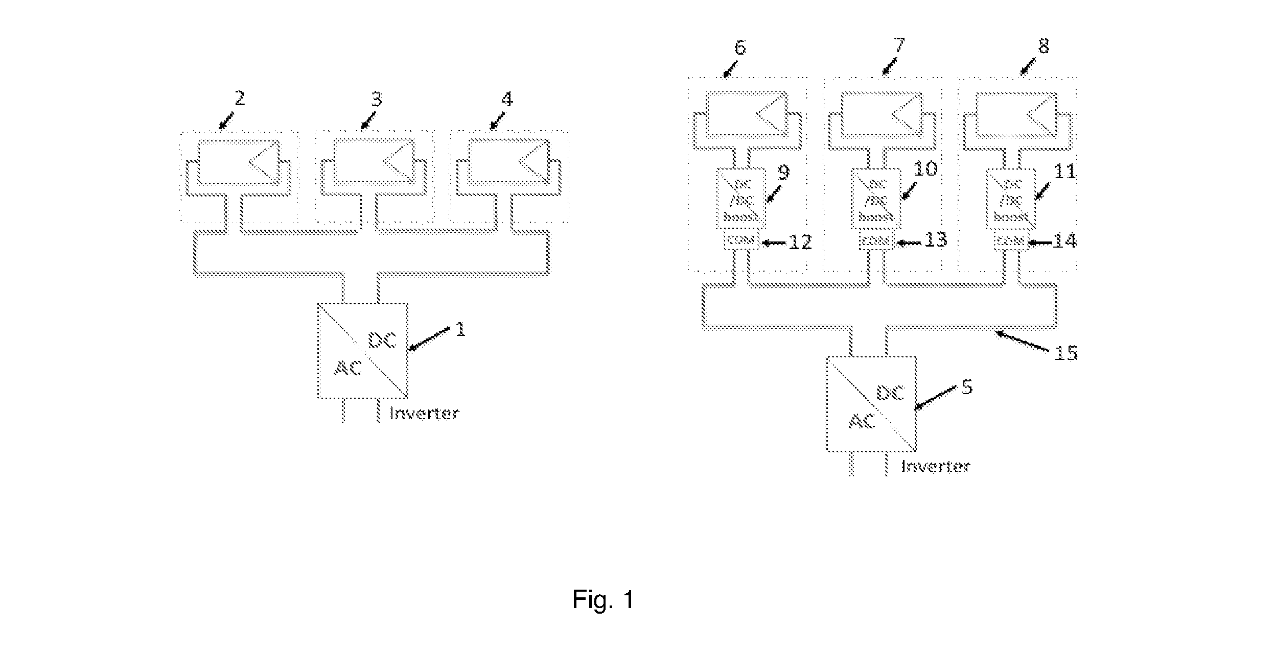
[0042]FIG. 1 is showing an example of the use of the invention in the context of a PV system. Over the last few years, performances improvements in the Photovoltaic markets drove the emergence of new technologies like micro-invertors and micro-convertors devices, which are becoming mainstream in the design of an energy efficient PV installation. The use of such devices allows to better compensating power lost due to various impairments such as shading, panel matching, soiling, etc. . .

[0043]FIG. 1 is showing a basic Photovoltaic approach leveraging a centralized DC / AC inverter 1 converting the unregulated generated DC power from the PV panels 2, 3 and 4.

[0044]One example of the benefits of the invention is wi...


PUM


Abstract

An apparatus is disclosed where a Powerline interface is used to transmitting data into the powerline grid network, where the powerline interface is pulling the required transmit energy from the power grid network, where the powerline interface is transmitting data using standard modulation such as ASK, FSK, S-FSK, QPSK, OFDM, etc. . . where the transmit data are passed on to the powerline interface by the use of an adapation stage, where a “control signal” is used to enable the transmitting of data by providing enough voltage to polarize the FET used in the control path.

Description

CROSS REFERENCE TO RELATED APPLICATION[0001]This application claims the benefits of priority under 35 U.S.C. 119© to the filing date of U.S. provisional patent application No. 61 / 495,924 entitled “New innovative Powerline Communication (PLC) solutions” which was filed Jun. 10, 2011 and is incorporated herein by reference.FIELD OF INVENTION[0002]The present invention relates to a new type of Powerline Communication interface, also called power line coupler, and more specifically to an ultra low power, low cost Powerline Interface (PI) between a PHY standard modulation, demodulation (MODEM) and the power wires used to connect all devices in their eco-system (Alternating Current [AC] or Direct Current [DC] depending on the application).BACKGROUND OF THE INVENTION[0003]As Utilities and other Energy Management Operators are looking at optimizing the electrical load of their grids and better manage energy peaks, “Intelligence” in the grid is making some in-road and is needed at every junc...

Claims


Application Information

Patent Timeline
IPC IPC(8): H04B3/54H04L27/04
CPCH04L25/0282H04B2203/5408H04L25/0272H04B2203/5445H04B3/544H04B2203/5412
Inventor BOIVIN, DIDIERGAETA, MICHAEL
Owner BOIVIN DIDIER
Why Eureka
Try Eureka