
Orientation system and method

Inactive Publication Date: 2012-12-13
DOTAN
View PDF12 Cites 11 Cited by
  • Summary
  • Abstract
  • Description
  • Claims
  • Application Information

AI Technical Summary

Benefits of technology

[0007]The disclosed solution permits to use low-cost commercial components to achieve high orientation precision and stable position holding by biasing a cable for preloading components of a mechanism and to form a one-way mechanism stable even against high external loads applied thereto.SUMMARY
[0008]It is an object of the present invention to provide a system and a method for operating a cable and a pulley mechanism, for orientation of a ring configured for rotation. The system includes a cable coupled to engage the ring, which is configured to rotate about a ring axis, a motor assembly including a motor coupled to a gearbox, which is rotated by the motor to provide a first rotation reduction, and a stretcher configured for stretching the cable.
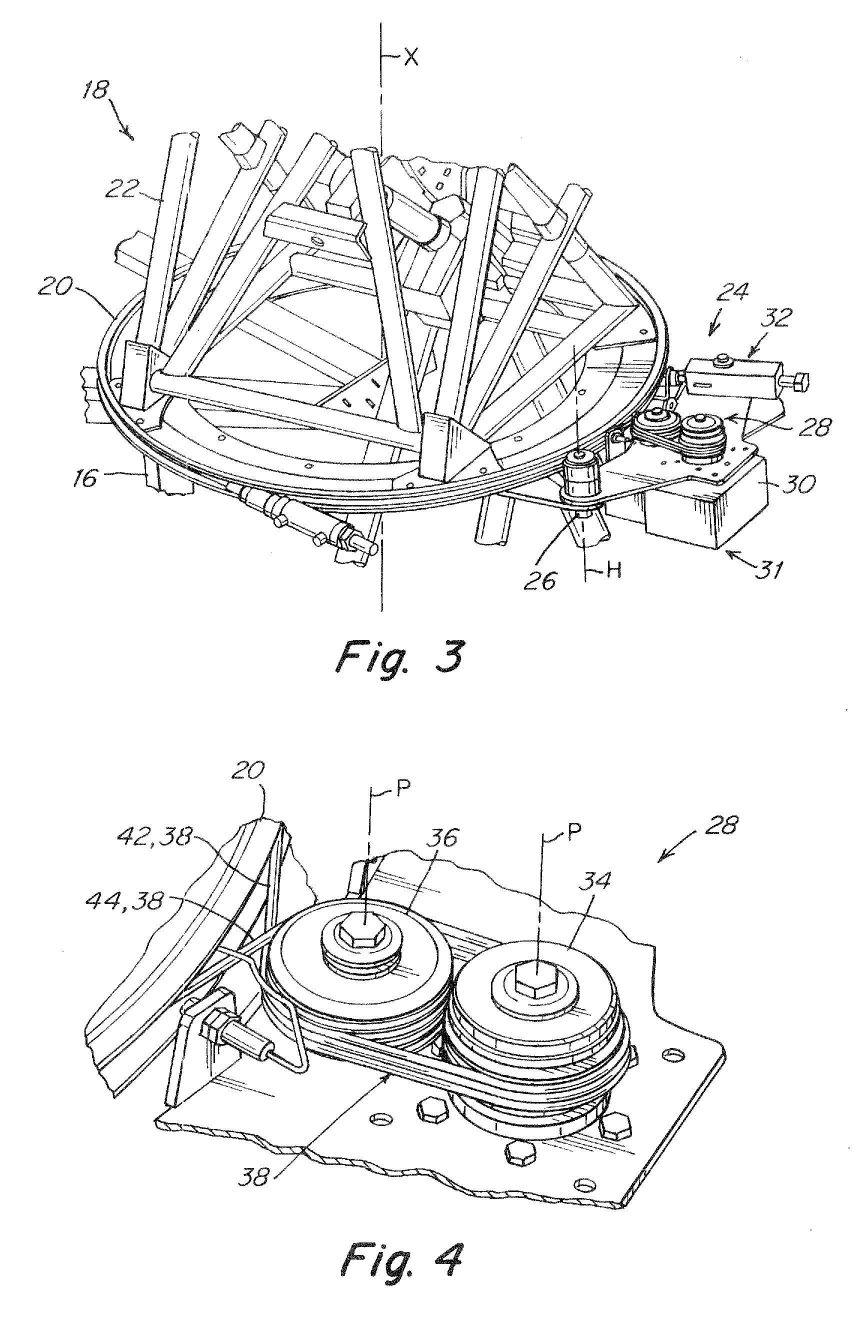
[0009]The system comprises a pulley assembly having a plurality of pulleys where each one pulley out of the plurality of pulleys is configured to rotate about a pulley axis. The pulley assembly includes an at least one proximal pulley disposed closer to the ring than an at least one distal pulley, where each pulley has a plurality of grooves configured for receiving the cable therein. The system further comprises a driving means disposed adjacent the ring, with the driving means being configured to support the pulley assembly, the motor assembly, and the stretcher in pivotal coupling about a hinge.
[0010]In addition, the system comprises the cable being engaged with the ring and with the at least one proximal and distal pulleys by being wound from a first groove in the proximal pulley to a first groove in the distal pulley and in repeated succession, to a next groove in the proximal pulley to a next groove in the distal pulley, until a last groove in the distal pulley, from where winding returns to the ring. The system also comprises the stretcher which is fixedly coupled to the driving means and is configured for pivoting the driving means distally away from the ring to stretch the cable and to bias the ring and the pulley assembly in preload.
[0011]Next, the ring is being rotated by the motor assembly, which is coupled to rotate the at least one distal pulley and provides a first reduction of rotation to the pulley assembly, which is configured and sized to provide a second reduction of rotation to the ring relative to motor rotation. Thereby, the ring is driven via at least a double reduction of rotation relative to rotation of the motor, and the cable engages the ring and the plurality of pulleys by friction.
[0012]It is a further object of the present invention to provide a method for operating a cable and a pulley mechanism for disposing a ring in a selected orientation. The method comprises providing a cable for engaging the ring and disposing the ring for rotation about a ring axis, providing a motor assembly including a motor coupled to and rotating a gearbox for providing a first rotation reduction drive, and providing a stretcher configured for stretching the cable.

Problems solved by technology

However, attempts to use such mechanisms for precise orientation of large objects have met with difficulties.

Method used


Image

  • Orientation system and method
  • Orientation system and method
  • Orientation system and method

Examples


Embodiment Construction

[0029]The embodiments described hereinbelow are described with reference to an exemplary embodiment selected as a system adapted to a tracking station. However, a method for operating a cable and a pulley mechanism for disposing a ring in a selected orientation may be used for other equipment requiring for example a large-size rotating ring requiring an open aperture having an interior diameter of large size.

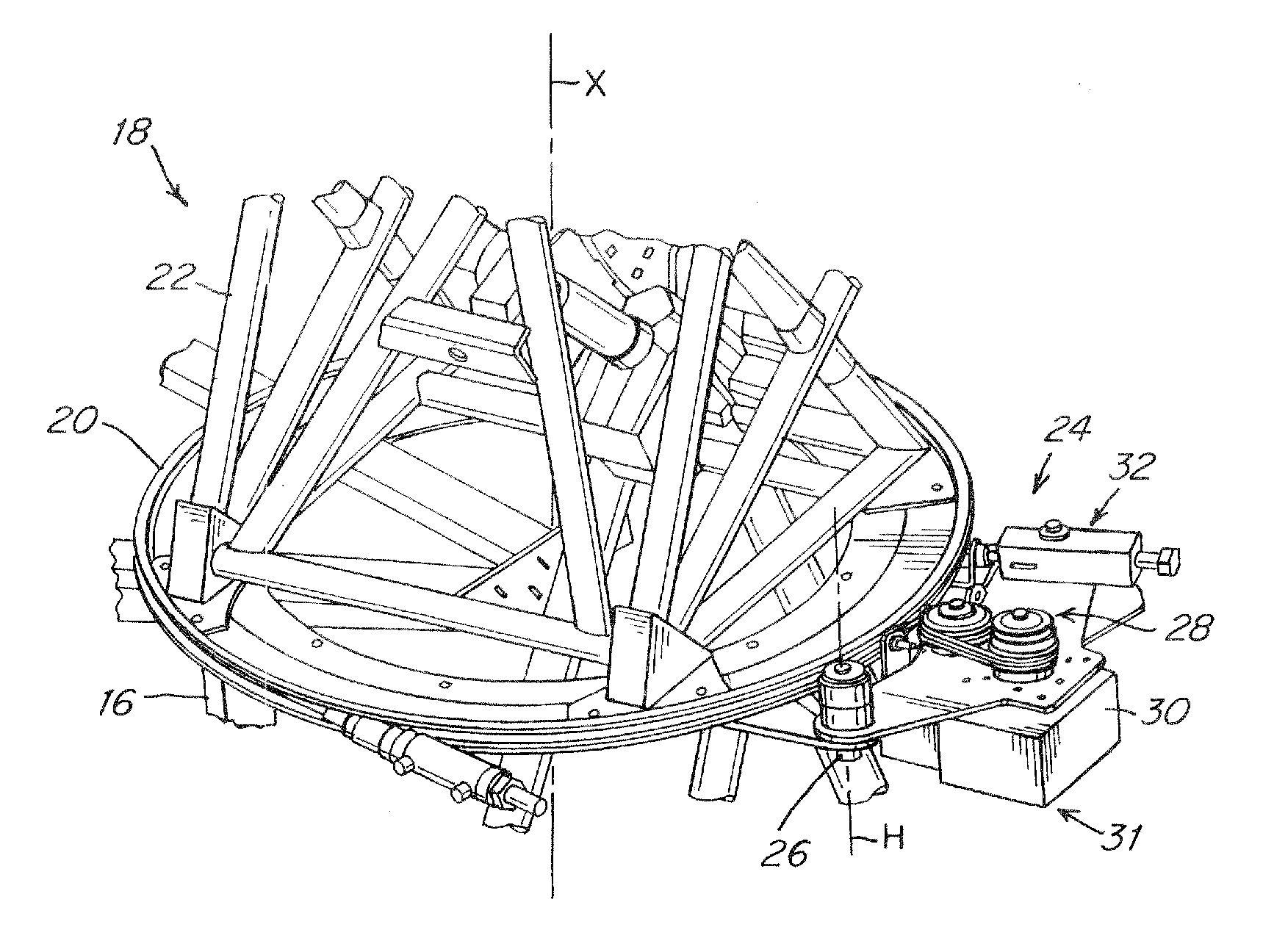
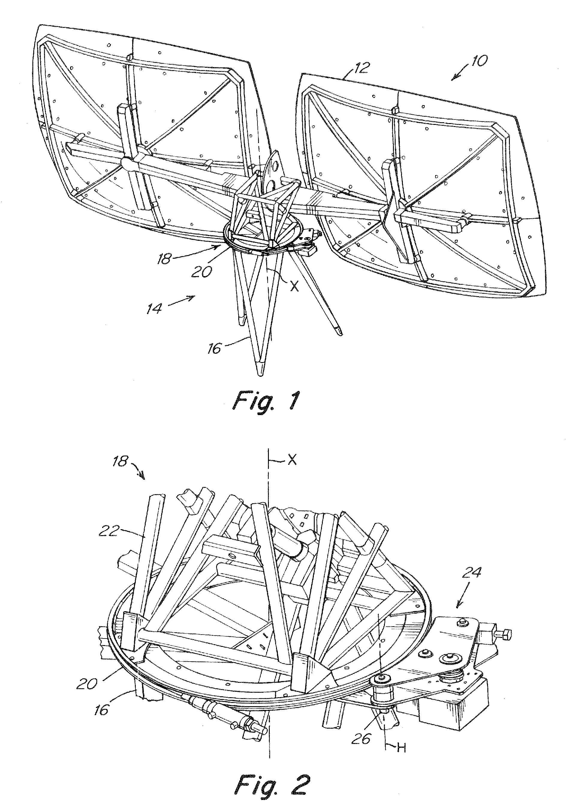
[0030]For example thus, FIG. 1 shows a tracking station 10, which has a tracking head 12 and a base 14. The tracking head 12 may be a solar concentrator for impinging rays of the sun to a particular point such as a photovoltaic cell, or an antenna such as a satellite dish for receiving and / or transmitting signals. The base 14 has a pedestal 16 and an adjuster 18 that is located on top of the pedestal 16. The pedestal 16 extends upright along an axis X in relation to a ground surface upon which it is disposed and the adjuster 18 is adapted to support the tracking head 12 at any o...


PUM


Abstract

A system and a method for orientation of a ring by rotation, including a cable engaging the ring which rotates about a ring axis, a motor assembly providing a first rotation reduction, and a stretcher for stretching the cable. The system has at least one proximal pulley and at least one distal pulley rotating about a pulley axis each pulley having grooves configured for receiving the cable therein. The ring is rotated by the motor assembly and the pulley assembly is configured to provide a second reduction of rotation to the ring relative to motor rotation, whereby the ring is driven via at least a double reduction of rotation relative to rotation of the motor, and the cable, the plurality of pulleys, and the ring provide a one-way mechanism.

Description

[0001]The present application claims benefit of International Application No. PCT / IL2010 / 001055 filed on 14 Dec. 2010, the priority date of which is claimed herein, and the entire contents of which is incorporated herein by reference.TECHNICAL FIELD[0002]The present invention relates to an orientation system and method, and in particular to the orientation and positioning of, for example, large size and heavy weight equipment, and of equipment, apparatus and instruments, in precise angular orientation and stable position holding against externally applied forces and eccentrically disposed loads.BACKGROUND ART[0003]Cable and pulley mechanisms are known per se for centuries. However, attempts to use such mechanisms for precise orientation of large objects have met with difficulties. For example, U.S. Pat. No. 5,990,843 to Roland H. Knapp recites a highly-stiffened, dual-axle antenna tracking pedestal for a satellite tracking station. In another example and for the same purpose. U.S. P...

Claims


Application Information

Patent Timeline
IPC IPC(8): F16H7/18F16H7/14
CPCF24J2/10F24J2/542Y02E10/47H01Q1/125H01Q3/04F24J2002/5458F24S23/70F24S2030/133F24S30/452
Inventor CHIEL, DAVID
Owner DOTAN
Learn More