Digital phase locked loop system and method

Active Publication Date: 2012-12-20
MEDIATEK INC
View PDF11 Cites 36 Cited by
  • Summary
  • Abstract
  • Description
  • Claims
  • Application Information

AI Technical Summary

Benefits of technology

[0005]The needs described above are fulfilled, at least in part, by use of a phase locked loop control system comprising a digital controlled ring oscillator that is controlled in response to comparison of the oscillator output with a reference clock related signal, by use of a digital phase and frequency detector. The ring oscillator frequency may be adjusted through a combination of varying the number delay cells coupled to the loop and

Problems solved by technology

However, such analog PLL circuits comprise a plurality of capacitors which require a significantly large chip area.
Additionally these circuits are very sensitive to power noise.
The frequency of

Method used


Image

  • Digital phase locked loop system and method
  • Digital phase locked loop system and method
  • Digital phase locked loop system and method

Examples


Embodiment Construction

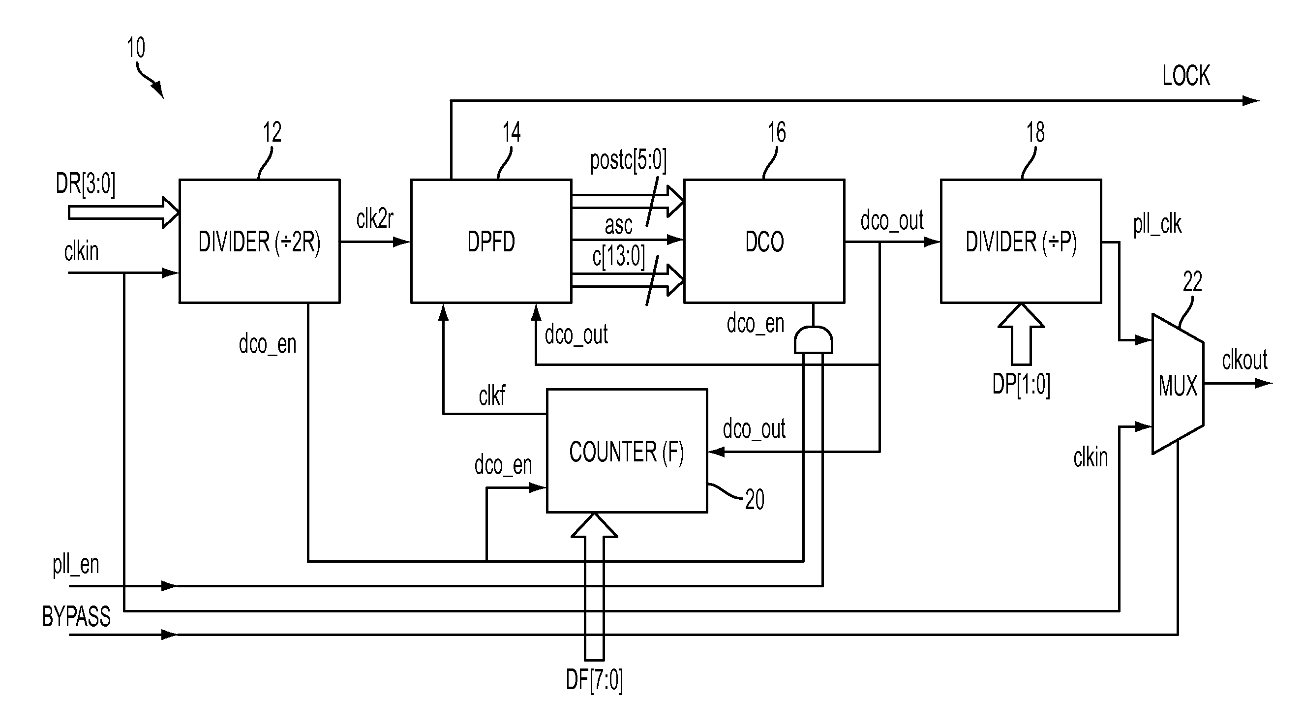
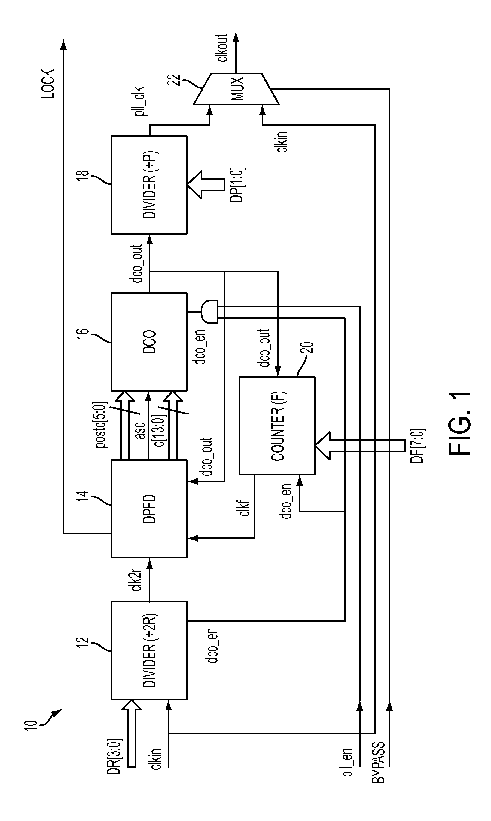
[0016]A digital controlled oscillator is controlled in response to comparison of the oscillator output with a reference clock related signal, by use of a digital phase and frequency detector. The cycling rate of the oscillator output is counted, the count is reset after a predetermined number of cycles, and the reset frequency is compared with the reference clock related signal.

[0017]An input divider can be coupled to the reference clock input for dividing the reference clock signal to one of a plurality of preset dividing rates. An output divider can be coupled to the oscillator output for dividing the oscillator output signal to one of a plurality of preset dividing rates. Each of the dividers may have a control input for selecting a respected dividing rate.

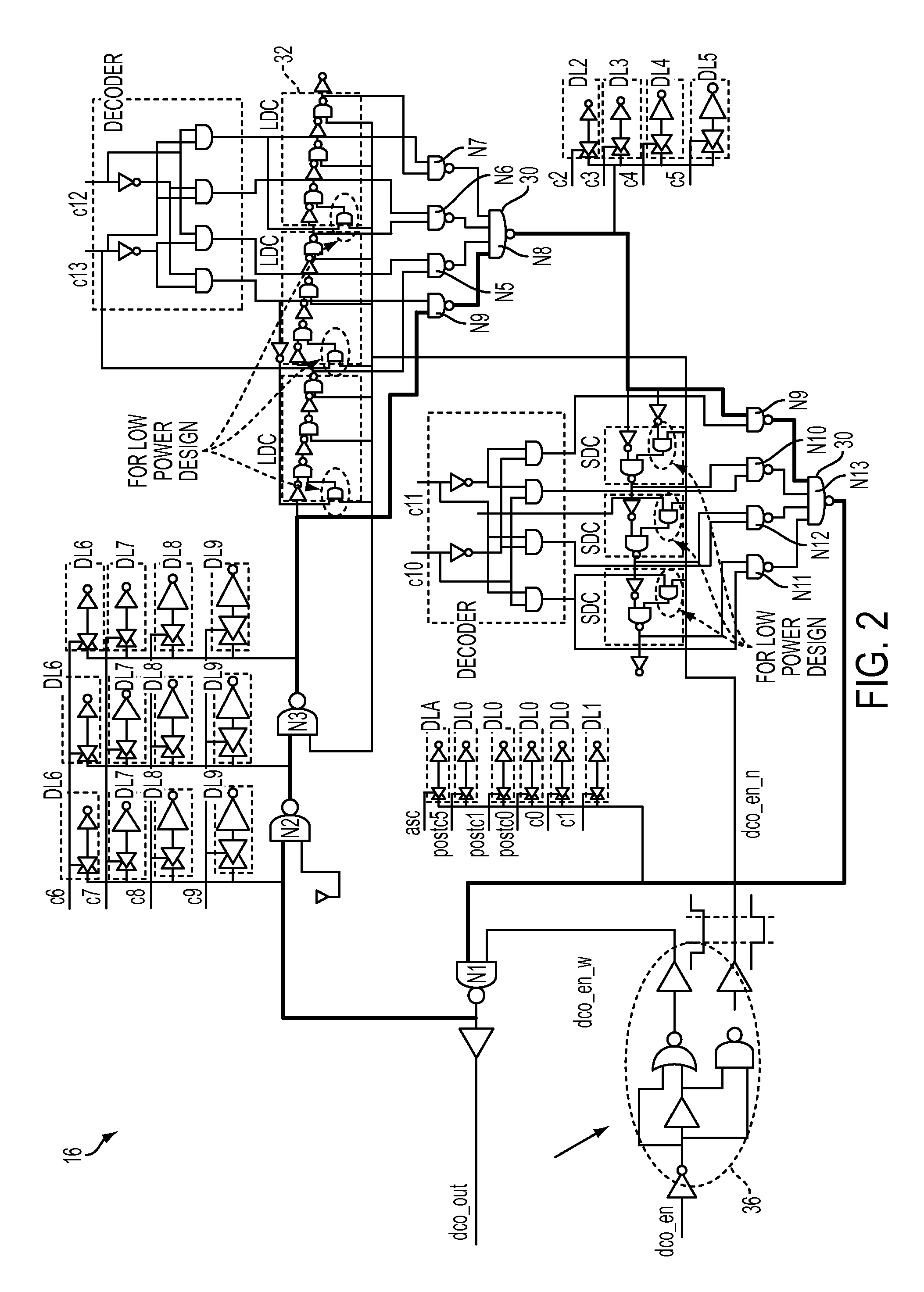
[0018]The digital controlled oscillator comprises a plurality of decoder logic cells. A first group of the decoder cells provide a relatively large signal delay; a second group of decoder cells provide a relatively smaller dela...


PUM


Abstract

A phase locked loop control system includes a digital controlled oscillator (DCO) that is controlled by logic cells in response to comparison of the oscillator output with a reference clock related signal. Delay cell number adjustment, delay cell load adjustment and cycle control are operative to digitally control the DCO frequency to obtain wide frequency range and limited jitter.

Description

BACKGROUND[0001]This disclosure is related to controlling an output signal with frequency and phase precisely related to the frequency and phase of an input “reference” signal, more particularly to phase locked loop (PLL) control.[0002]PLL control circuits are widely used in radio, telecommunications, computers and other electronic applications. They may generate stable frequencies, recover a signal from a noisy communication channel, or distribute clock timing pulses in digital logic designs such as microprocessors. Traditionally, the PLL circuit has been an analog block, including the basic components of a voltage control oscillator (VCO), phase and frequency detector (PFD), charge pump, low pass filter (LPF) and a feedback path. However, such analog PLL circuits comprise a plurality of capacitors which require a significantly large chip area. Additionally these circuits are very sensitive to power noise.[0003]More recently, PLL circuit design has evolved to a greater use of digit...

Claims


Application Information

Patent Timeline
IPC IPC(8): H03L7/06
CPCH03L7/085H03L7/0991H03L2207/50H03L7/183H03L7/10H03L7/099
Inventor LUO, ZHIHONG
Owner MEDIATEK INC
Why Eureka
Try Eureka