Manufacturing method of common mode filter and structure of the same

a technology of common mode filter and manufacturing method, which is applied in the direction of transformer/inductance details, basic electric elements, inductance, etc., can solve the problems of difficult manufacturing of the minimized components, easy cracking of the magnetic composite substrate of the common mode filter, and still has problems, so as to achieve easy mass production, reduce the volume of the common mode filter, and support stable

Inactive Publication Date: 2012-12-20
ADVANCE FURNANCE SYST CORP
View PDF7 Cites 9 Cited by
  • Summary
  • Abstract
  • Description
  • Claims
  • Application Information

AI Technical Summary

Benefits of technology

[0007]Therefore it is a primary object of the present invention to provide a manufacturing method of common mode filters and a structure of the same. The common mode filter includes a composite substrate and a common mode choke layer produced by a wafer-level electrode leading out method. The composite substrate consists of a baser layer with an adhesive layer and a first magnetic material layer arranged over the adhesive layer. The base layer and the first magnetic material layer are sintered and connected by the adhesive layer. The common mode choke layer is composed of a plurality of inductive coils and a plurality of insulated layers while the inductive coil includes at least a pair of leading-out terminals located on sides thereof. Moreover, a second magnetic material layer is coated on an upper surface of the common mode choke layer. Then by partial cutting, sputtering, lithography, and electroplating at wafer level, external electrodes are formed on sides of the common mode choke layer, corresponding to the leading-out terminals. Thereby the composite substrate has more stable support. The volume of the common mode filter is minimized due to the inductive coils and external electrodes connected by wafer level packaging. Thus the common mode filter becomes compact and easy to be mass-produced. The cost is down and the rejection rate is also reduced. At the same time, the inductive coils and the external electrodes are connected by packaging techniques such as sputtering, lithography and electroplating at wafer level. The reliability problem of the electrodes produced by conventional silver plating is reduced. The common mode filter of the present invention is of higher practical value.

Problems solved by technology

The manufacturing of the minimized components is difficult.
Although the above common mode filter provides expected effects, it still has problems.
However, a magnetic composite substrate of the common mode filter is easy to get cracked during clamping of manufacturing processes due to weak strength.
And during the cutting process, the common mode filters are easy to get damaged and this results in additional cost / loss.
Moreover, reliability of the external electrode is a problem.

Method used


Image

  • Manufacturing method of common mode filter and structure of the same
  • Manufacturing method of common mode filter and structure of the same
  • Manufacturing method of common mode filter and structure of the same

Examples


Embodiment Construction

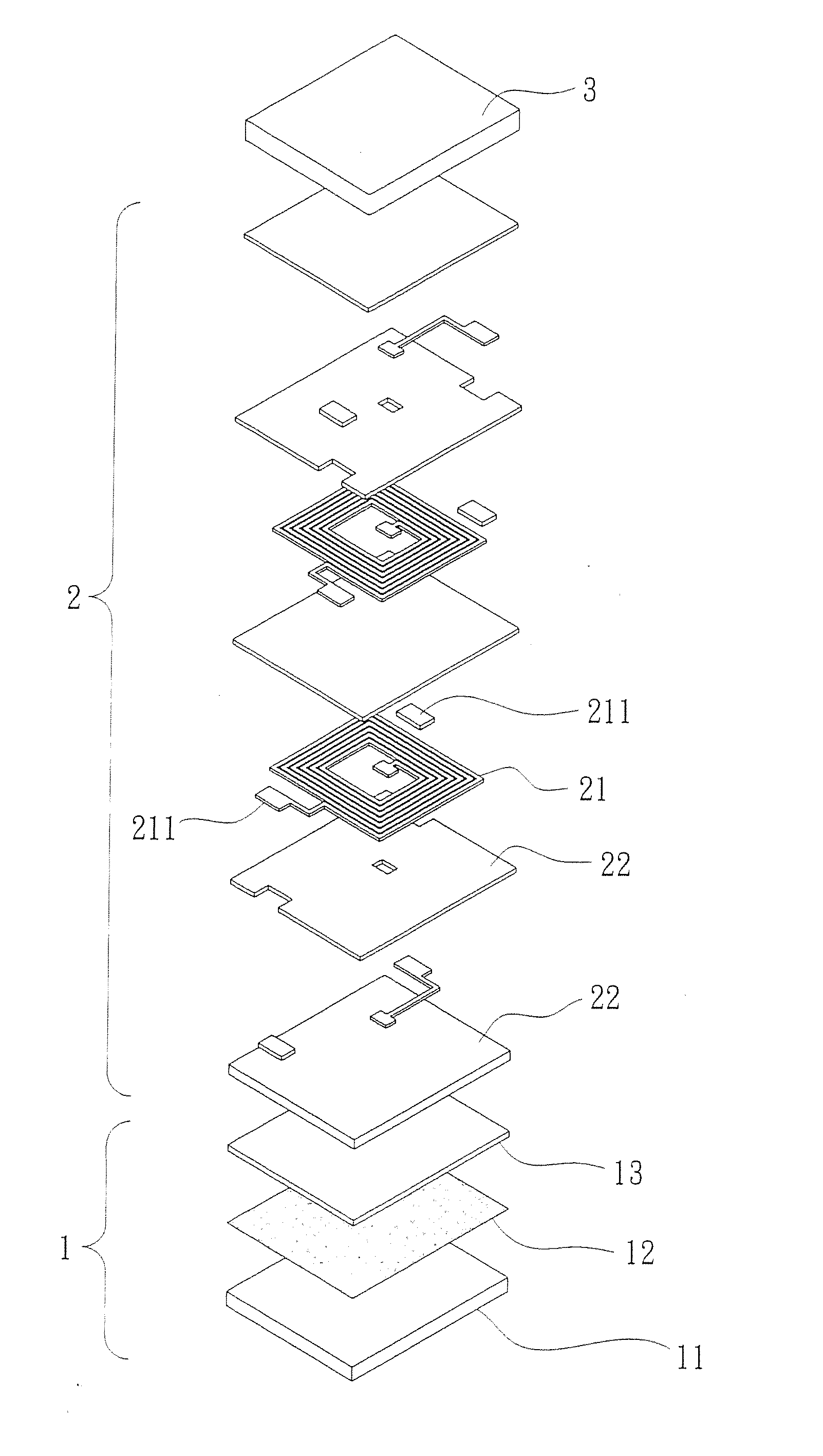
[0023]Refer to FIG. 1, a common mode filter of the present invention mainly includes a composite substrate 1, a common mode choke layer 2, and a second magnetic material layer 3.

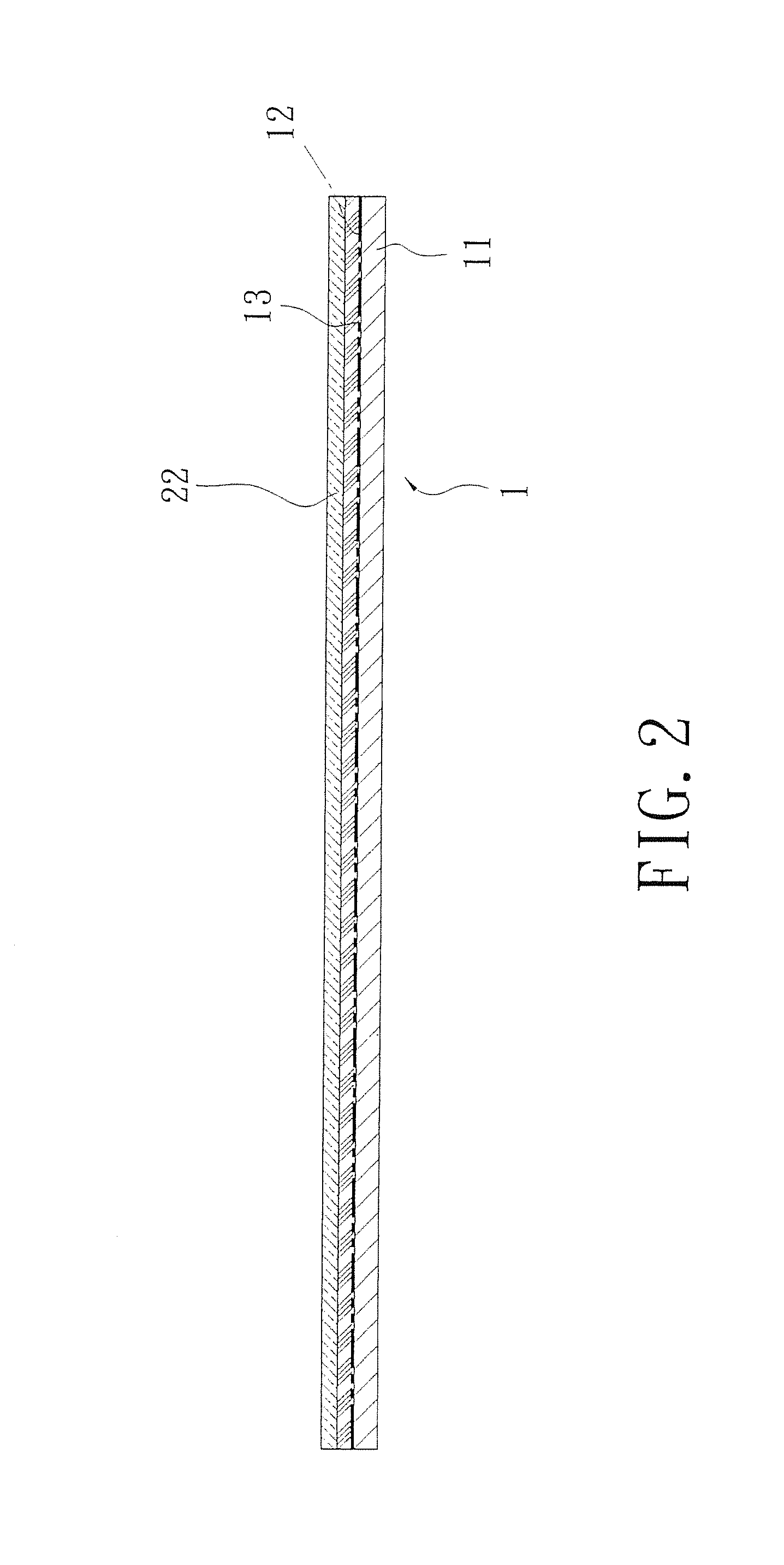
[0024]Refer to FIG. 2, the composite substrate 1 consists of a base layer 11 made from alumina (Al2O3), or silicon (Si) and an adhesive layer 12 disposed over the base layer 11. The adhesive layer 12 is coated with a first magnetic material layer 13. In consideration of the flatness, the first magnetic material layer 13 is made from magnetic material whose particle size is smaller than 10 μm. And the thickness of the first magnetic material layer 13 ranges from 20 μm to 80 μm. The base layer 11 and the first magnetic material layer 13 are sintered and connected with each other by the adhesive layer 12.

[0025]The common mode choke layer 2 is composed of a plurality of inductive coils 21 and a plurality of insulated layers 22. The inductive coil 21 includes at least a pair of leading-out terminals 211.

[0026]The...


PUM

PropertyMeasurementUnit
thicknessaaaaaaaaaa
thicknessaaaaaaaaaa
particle sizeaaaaaaaaaa

Abstract

A manufacturing method of common mode filters and a structure of the same are revealed. A common mode choke layer is disposed over a composite substrate and a second magnetic material layer is coated on an upper surface of the common mode choke layer. The common mode choke layer is produced by a wafer-level electrode leading out method and having leading-out terminals on sides thereof. External electrodes are formed on sides of the common mode choke layer by partial cutting, sputtering, lithography and electroplating at wafer level and corresponding to the leading-out terminals. Thereby common mode filters produced are supported more stably. Moreover, the volume is minimized due to inductive coils and external electrodes connected by wafer level packaging. Thus the common mode filters are mass-produced, the cost is down and the defect rate is reduced.

Description

RELATED APPLICATIONS[0001]This application is a Divisional patent application of application Ser. No. 13 / 248,075, filed on 29 Sep. 2011, now pending. The entire disclosure of the prior application Ser. No. 13 / 248,075, from which an oath or declaration is supplied, is considered a part of the disclosure of the accompanying Divisional application and is hereby incorporated by reference.BACKGROUND OF THE INVENTION[0002]1. Field of the Invention[0003]The present invention relates to a manufacturing method of common mode filters and a structure of the same, especially to a common mode filter that provides more stable support by a composite substrate and connects inductive coils with external electrodes by wafer scale packaging techniques for minimization of the volume. Once the common mode filters are of compact size, they can be mass-produced, the cost is reduced and the defect rated is decreased. At the same time, the connection and conduction between the inductive coils and the extern...

Claims


Application Information

Patent Timeline
Patent Type & Authority Applications(United States)
IPC IPC(8): H01F5/00
CPCH01F17/0013H01F27/292H01F2017/0066Y10T29/49208Y10T29/5313Y10T29/4902Y10T29/49002
Inventor CHU, CHUNG-MING
Owner ADVANCE FURNANCE SYST CORP
Why Eureka
Try Eureka