
Multiple-Symbol Polarization Switching for Differential-Detection Modulation Formats

a multi-symbol polarization and modulation format technology, applied in the field of optical communication, can solve the problems of limited maximum reach, low hardware resource requirements, and low hardware resource requirements of existing dsp-based fiber nonlinearity mitigation algorithms,

Inactive Publication Date: 2012-12-20
NEC CORP
View PDF23 Cites 12 Cited by
  • Summary
  • Abstract
  • Description
  • Claims
  • Application Information

AI Technical Summary

Benefits of technology

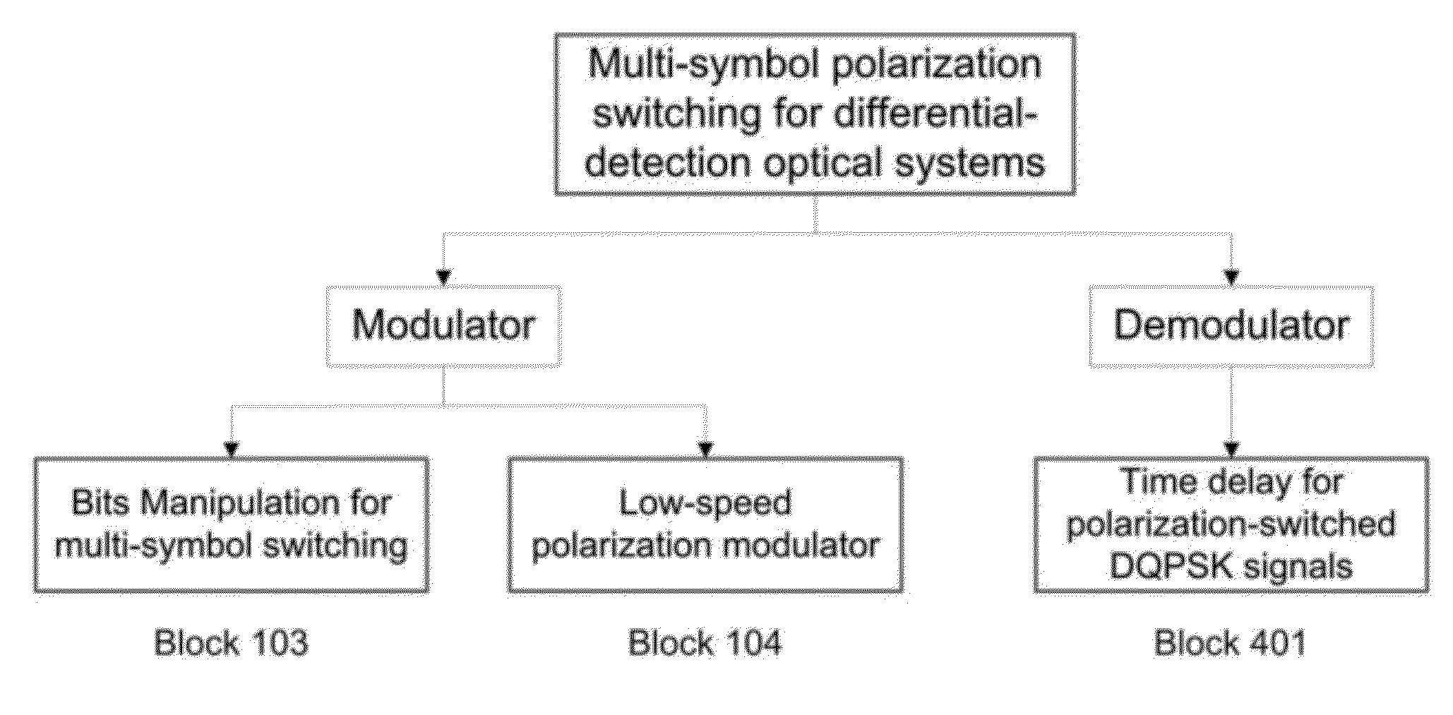
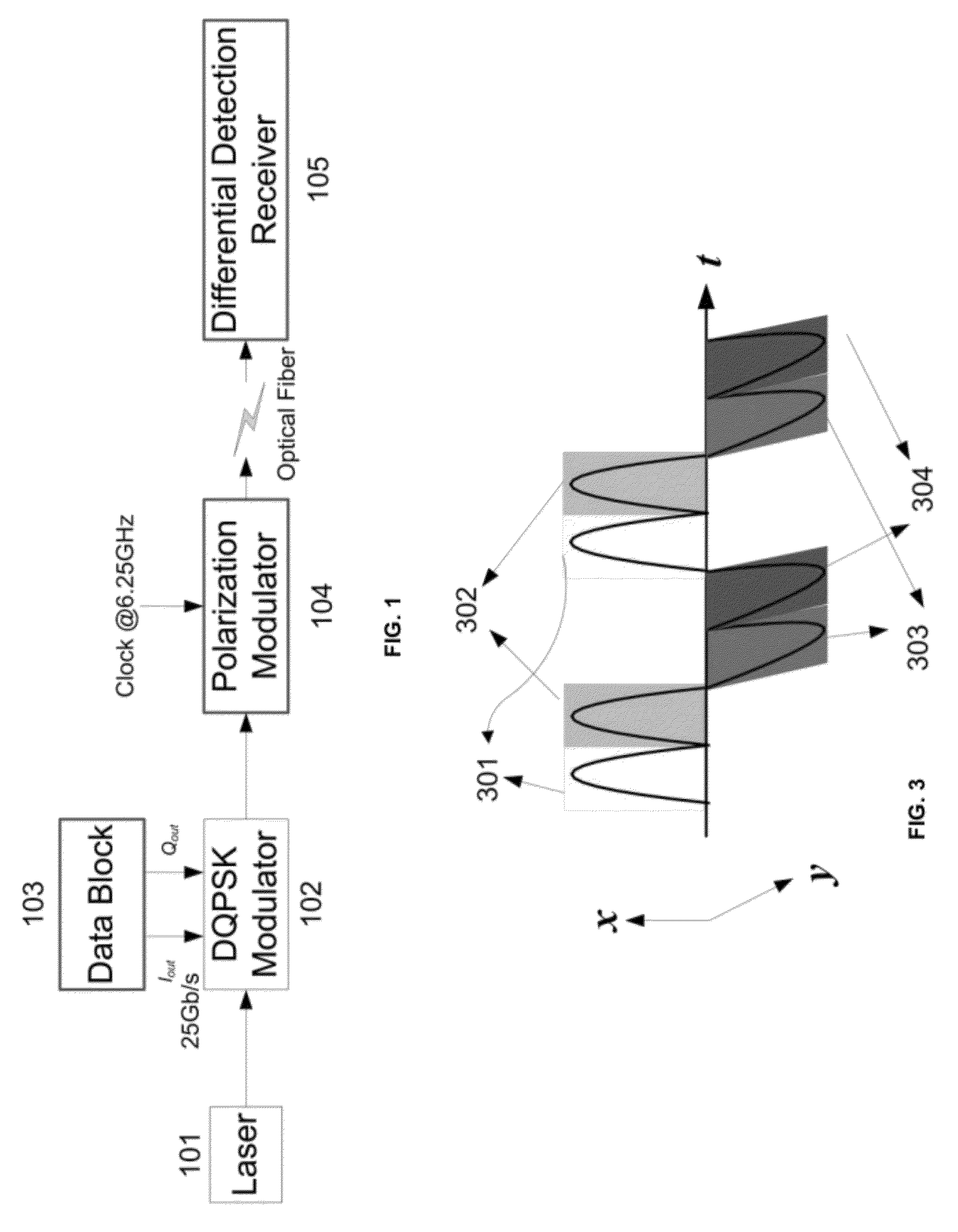
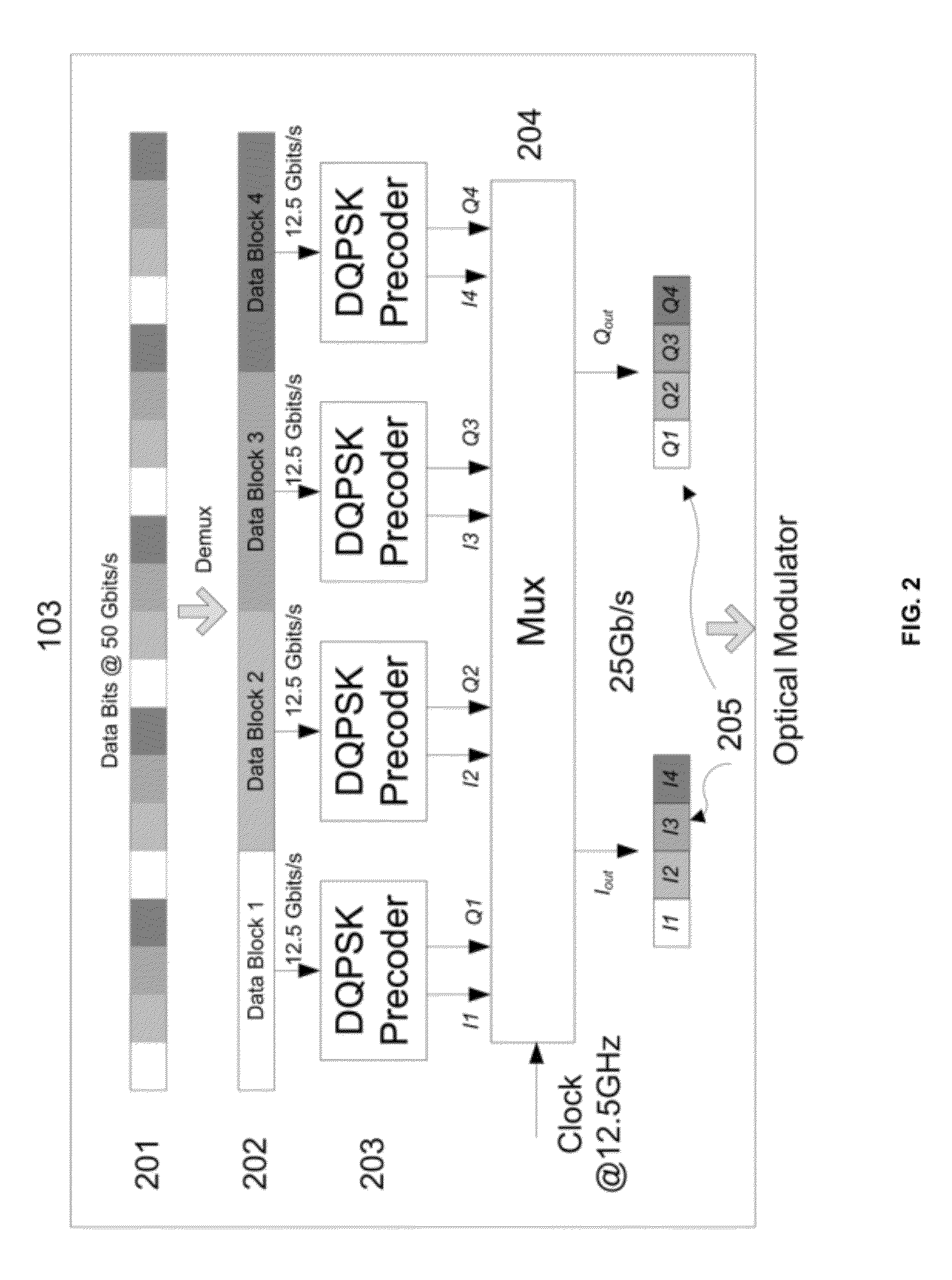
[0007]In an aspect of the present invention, a method for multi-symbol polarization switching for differential detection optical systems includes modulating a laser source by a DQPSK modulator, driving the DQPSK modulator with a data block configured for generating multi-symbol polarization-switched DQPSK differential-encoded signals, and polarizing the multi-symbol polarization-switched DQPSK signals with a polarizing modulator whose modulation speed is based on how often polarization states vary, wherein the data block provides a bits manipulation to provide the multi-symbol polarization switching thereby enabling differential detection for recovering correct original data by a receiver.

Problems solved by technology

However, one of the major challenges facing the ultra-high-data-rate dense wavelength division multiplexing (DWDM) optical fiber transmissions is the fiber nonlinearity, which causes optical signal distortions due to the various nonlinear effects in optical fiber and sets the limit of the maximal reach.
However, the existing DSP-based fiber nonlinearity mitigation algorithms are demanding on the hardware resources, which are relatively limited and sophisticated due to the requirements of very high electronic processing bandwidth.
Meanwhile, most of the existing nonlinearity mitigation algorithms show very limited system performance improvements in real experimental testing.
However, the deployment of this scheme requires at the exact middle point of the entire transmission link, thus imposing a strict and thus unpractical restrictions on the system deployment.

Method used


Image

  • Multiple-Symbol Polarization Switching for Differential-Detection Modulation Formats
  • Multiple-Symbol Polarization Switching for Differential-Detection Modulation Formats
  • Multiple-Symbol Polarization Switching for Differential-Detection Modulation Formats

Examples


Embodiment Construction

[0014]It is suggested in prior literatures that using polarization switching should increase the nonlinearity tolerance of optical communication signals. If the two neighboring symbols are located at orthogonal polarization states, the inter-symbol interference between the two neighboring symbols does not generate coherent beating, and thus suffers from reduced nonlinear distortions. The modification to current system structure is relatively small and it can be readily applied in different direction-detection systems. In this invention record, we focus on RZ-DQPSK format, which is popular for 40 Gb / s-based long-haul optical communication systems. Compared to OOK format, the differential precoding and decoding in DQPSK / DPSK would require additional arrangement. We systematically describe the design of transmitter and receiver in this proposed multi-symbol polarization-switching scheme. Introducing polarization switching by several symbols is proven capable of mitigating the inter-sym...


PUM


Abstract

An inventive method for multi-symbol polarization switching for differential detection optical systems includes modulating a laser source by a DQPSK modulator, driving the DQPSK modulator with a data block configured for generating multi-symbol polarization-switched DQPSK differential-encoded signals, and polarizing the multi-symbol polarization-switched DQPSK signals with a polarizing modulator whose modulation speed is based on how often polarization states vary, wherein the data block provides a bits manipulation to provide the multi-symbol polarization switching thereby enabling differential detection for recovering correct original data by a receiver.

Description

[0001]This application claims the benefit of U.S. Provisional Application No. 61 / 497,989, entitled “Multiple Symbol Polarization Switching Differential-Detection Modulation Formats”, filed Jun. 17, 2011, of which the contents are incorporated herein by reference.BACKGROUND OF THE INVENTION[0002]The present invention relates generally to optical communications and, more particularly, to multiple symbol polarization switching differential-detection modulation formats.[0003]As Internet traffic grows exponentially because of a variety of user terminals and internet services, it has prompted strong research interests on high-speed optical networks, which are the backbone infrastructure of current “Globe Village”. The data rate for optical fiber communications has moved from 10 Gbits / s to 40 Gb / s and 100 Gbits / s or even 1 Tbits / s per channel. However, one of the major challenges facing the ultra-high-data-rate dense wavelength division multiplexing (DWDM) optical fiber transmissions is th...

Claims


Application Information

Patent Timeline
IPC IPC(8): H04Q11/00
CPCH04Q2213/1301H04B10/532H04B10/5561H04L27/2075H04L27/2096H04L27/223H04Q11/00
Inventor ZHANG, SHAOLIANGYAMAN, FATIHXU, LEIWANG, TINGINADA, YOSHIHISAOGATA, TAKAAKIAOKI, YASUHIRO
Owner NEC CORP
Learn More